Data Center Power Systems: UPS, Generators and Power Distribution for Enterprise
Data Center Power Systems: UPS, Generators and Power Distribution for Enterprise
Enterprise-grade data center power systems succeed when the entire electrical chain—utility intake, medium-voltage distribution, UPS, generators, switchgear, and rack-level delivery—works as one coordinated, testable system. The practical goal is simple: predictable uptime under failures, maintainability without service interruption, and measurable efficiency under real load profiles. Achieving that requires not only correct topology (N+1, 2N, or distributed redundancy), but also disciplined engineering standards, commissioning routines, and lifecycle service.
If you are planning a new build or expanding capacity, contact Lindemann-Regner for a technical consultation and budgetary quotation. We combine German engineering discipline with globally responsive delivery to help you standardize design, reduce integration risk, and accelerate deployment.
Global Data Center Power Architecture from Utility Feed to Rack
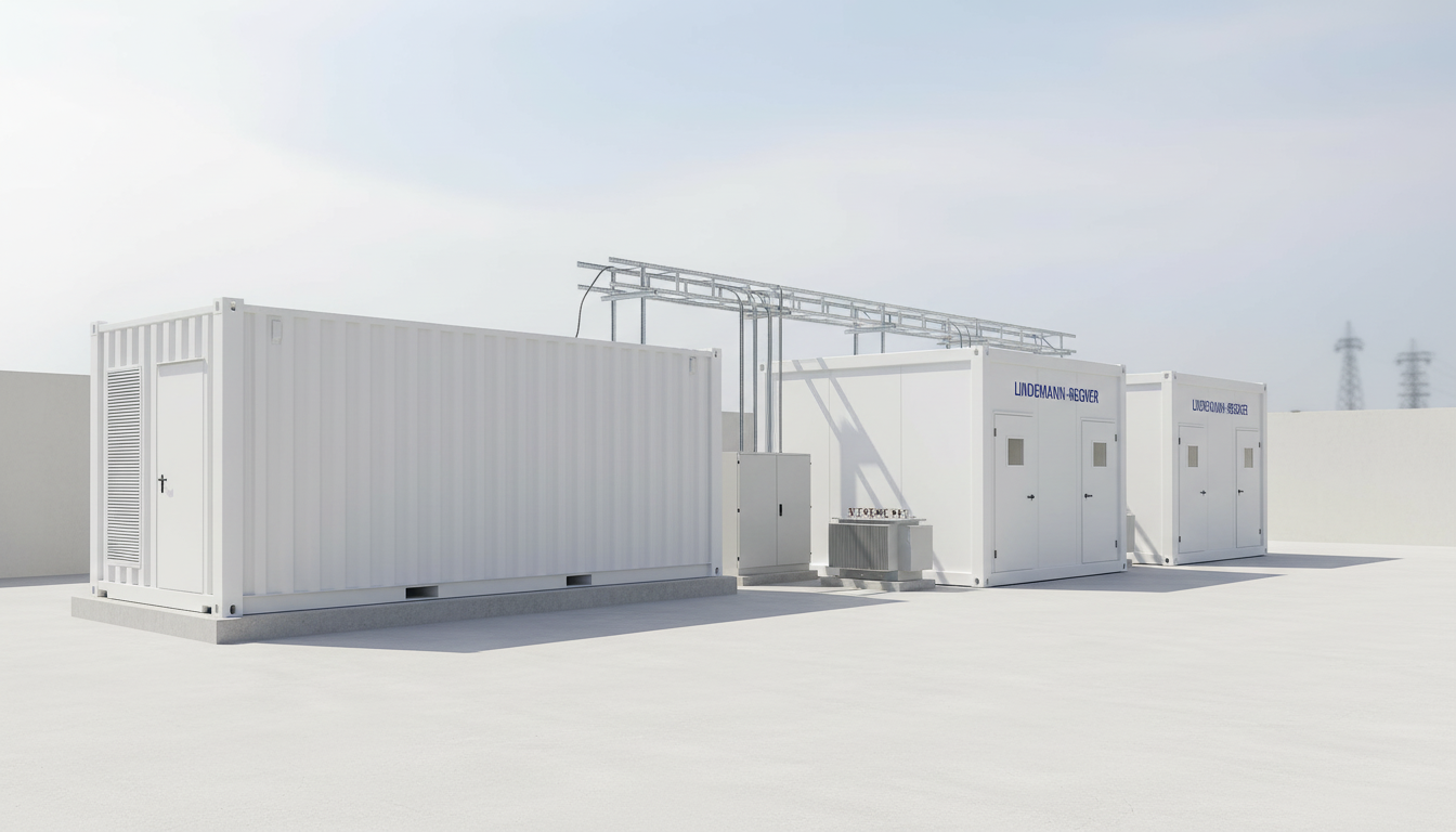
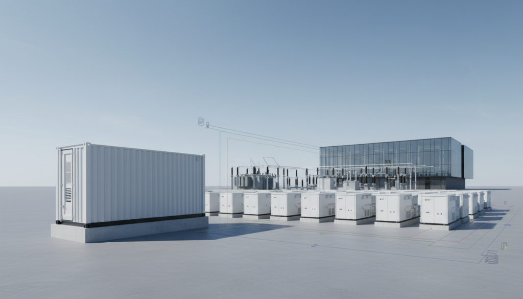
A robust architecture starts at the point of common coupling and extends all the way to the IT load. In most enterprise facilities, the chain includes utility MV intake, MV switchgear, transformers stepping down to LV, LV switchboards, UPS modules, static transfer paths where applicable, generator plant with paralleling gear, and finally branch circuits feeding rack PDUs. The “global” aspect is not only geography; it is also repeatable reference design—consistent single-line diagrams, protection coordination, and test procedures that can be replicated across sites.
From an engineering perspective, the most common weak points are interfaces: where the utility hands off to the operator, where MV becomes LV, where UPS output feeds critical distribution, and where ATS/STS logic intersects with generator dynamics. Designing these interfaces with clear selectivity and isolation boundaries improves maintainability and reduces the chance that a localized fault escalates into a site-wide outage. A practical rule is to ensure every critical segment has both a protection strategy (fault clearing) and an operational strategy (safe isolation and restoration).
A second foundation is capacity planning with realistic diversity factors. Enterprise data centers frequently overestimate “nameplate IT load” and underestimate inrush, harmonics, and growth asymmetry between rooms. Architecture should therefore include metering at each major node (MV, LV, UPS input/output, generator output, PDU) so that expansion is based on measured data. This also sets you up for better PUE management and prevents “hidden” overloads at distribution bottlenecks.
UPS Systems and Generator Integration for Enterprise Uptime
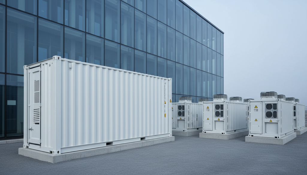
UPS selection is not just about kVA—it is about dynamic behavior under disturbances. Modern enterprise UPS deployments typically use modular double-conversion systems for scalability and serviceability, while some use distributed UPS at the row or room level for fault containment. The integration question is how the UPS ride-through profile matches generator start, synchronization, and step-load response. A well-designed system ensures the UPS never has to absorb generator instability longer than its intended autonomy window.
Generator integration must be treated as a controlled system, not a set of standalone machines. Paralleling gear, load sharing logic, and black-start sequencing influence how quickly and cleanly the facility transitions from utility to island mode. In practice, the most valuable design work happens around transfer logic, breaker interlocks, and the exact testing regime: monthly no-load tests are not enough; you need periodic load bank or “real load” tests to validate the combined behavior of UPS, switchgear, and generators.
Battery technology also affects uptime economics. VRLA remains common, but lithium-ion is increasingly selected where footprint, thermal management, and lifecycle replacement costs drive decisions. Regardless of chemistry, enterprise uptime depends on monitoring: cell-level analytics, string impedance trends, and clear replacement thresholds. UPS without rigorous battery governance is a perceived redundancy rather than a proven one.
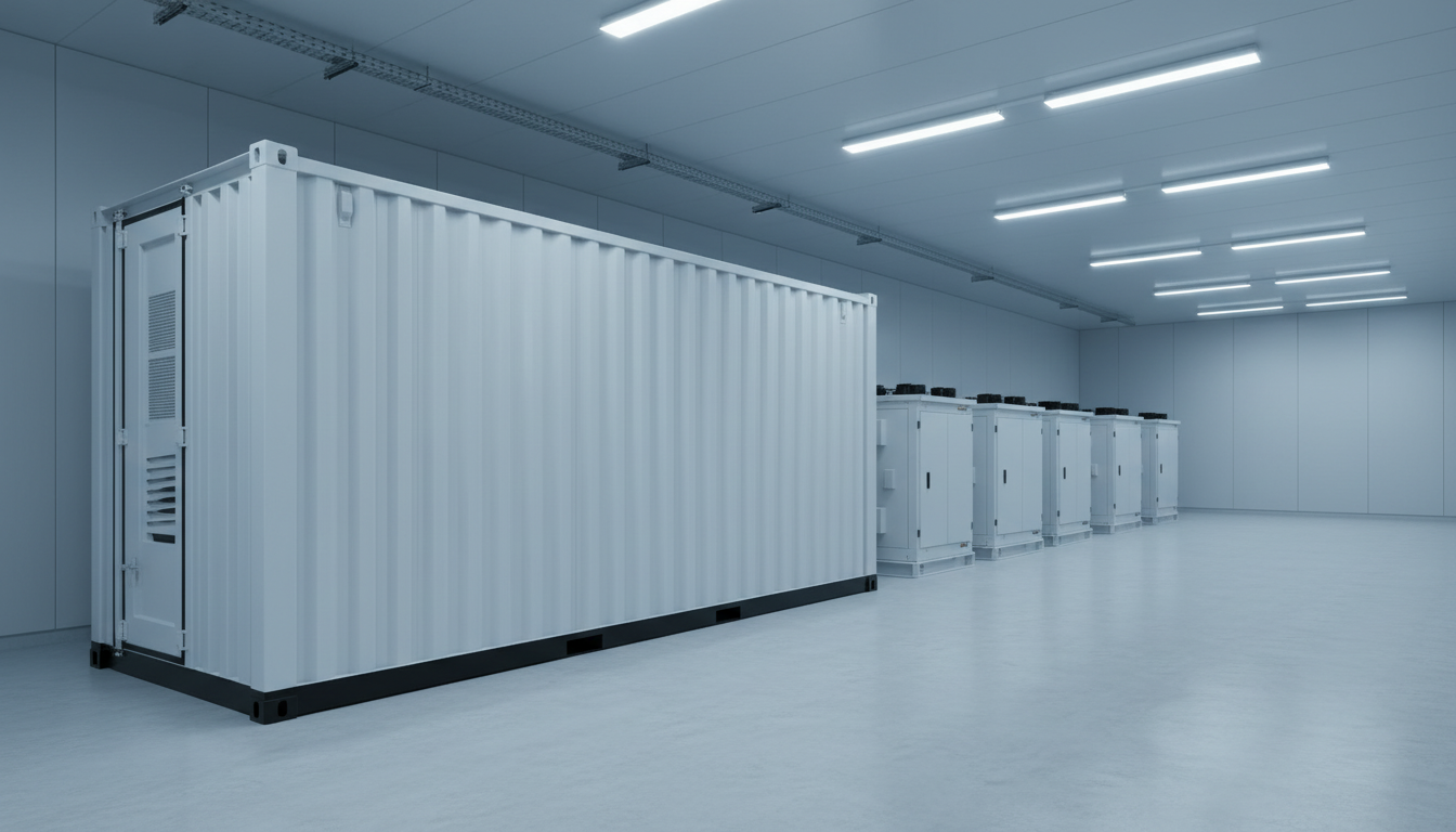
Rack PDUs, Switchgear and ATS in Modern Data Center Power
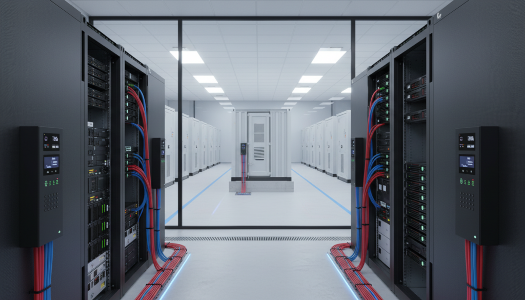
At the rack level, power delivery quality is ultimately experienced as breaker trips, thermal hotspots, and maintenance constraints. Intelligent rack PDUs provide metering down to outlet or branch level, which supports both capacity planning and chargeback in colocation-like internal models. The practical design question is how you segment and label A/B feeds, how you prevent accidental cross-connection, and how you ensure that maintenance on one path does not compromise the other.
Upstream, switchgear is where selectivity and maintainability are either achieved or lost. For modern data center power systems, you want clearly defined critical and non-critical buses, maintainable UPS output distribution, and well-documented interlocks for safe switching. ATS is still widely used for generator transfer, but in higher availability designs you also see STS applications for fast source transfer in specific distribution points—each with different implications for fault behavior and coordination.
A frequent enterprise improvement is to align protective device settings with real short-circuit studies and harmonic profiles, rather than using vendor defaults. That reduces nuisance trips and improves fault isolation. Equally important is physical layout: segregated cable routes, thermal spacing in switchboards, and service clearances that allow component replacement without shutting down adjacent gear.
| Component | Role in the power chain | Key design focus | Typical risk if misapplied |
|---|---|---|---|
| MV/LV switchgear | Fault isolation + operational switching | Selectivity, interlocks, maintainability | Cascading trips, unsafe switching |
| ATS / STS | Source transfer | Transfer logic, coordination, testing | Unwanted transfers, instability |
| Rack PDU | Last-metered delivery to IT | A/B feed discipline, outlet metering | Hidden overload, poor capacity visibility |
| Busway / RPP | Flexible distribution | Modularity, labeling, expansion | Hotspots, misfeeds |
This table helps map where “availability engineering” happens in practice: each node must be designed for both electrical fault behavior and human maintenance behavior. In many enterprise sites, reliability issues stem from operational complexity rather than insufficient equipment rating.
Designing Redundant Data Center Power for Tier III and Tier IV
Tier-aligned design is about concurrent maintainability (Tier III) and fault tolerance (Tier IV), but the real-world success factor is whether the topology is correctly implemented end-to-end. For Tier III intent, you typically design N+1 at critical components and ensure any single component can be taken out of service without impacting the IT load. That means not only redundant UPS modules, but also maintainable distribution paths, bypass arrangements, and isolation points that do not require a full shutdown.
Tier IV-like fault tolerance usually implies 2N or distributed 2(N+1) architectures, with physical and electrical separation to avoid common-mode failures. Enterprises adopting this level of redundancy must pay extra attention to common dependencies such as control power, cooling, fuel systems, and even room-level fire protection interactions. A “2N electrical” design can still be vulnerable if both paths share a single control panel, a single cable trench, or a single human procedure that invites error.
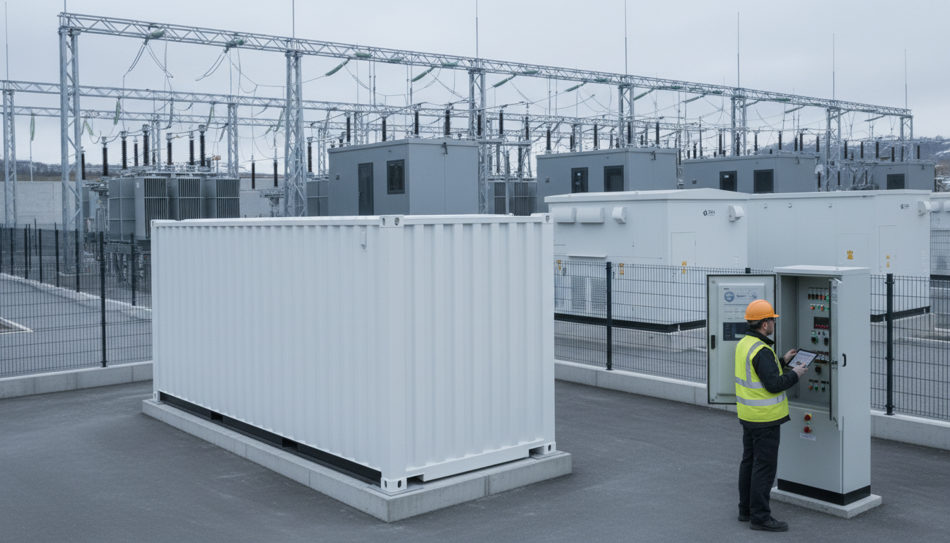
Commissioning and integrated systems testing (IST) are where Tier intent becomes proof. Step-load tests, simulated breaker failures, and maintenance scenarios should be executed with documented acceptance criteria. The strongest enterprise programs treat IST as a lifecycle practice: repeatable scripts, annual regression tests after expansions, and disciplined change management.
| Redundancy model | Typical enterprise fit | Strength | Trade-off |
|---|---|---|---|
| N+1 | Many enterprise private DCs | Good balance of cost and availability | Requires high operational discipline |
| 2N | Mission-critical enterprise / regulated | High resilience to single failures | Higher CAPEX/OPEX and footprint |
| 2(N+1) | Very high uptime targets | Handles failures + maintenance gracefully | Complexity and integration effort |
A topology choice is only “right” when it matches business impact analysis, maintenance maturity, and growth plans. Overbuilding redundancy without operational readiness can increase outage probability due to complexity.
Energy Efficiency, PUE and Sustainable Data Center Power Options
Electrical efficiency is increasingly a board-level topic because it drives both cost and carbon reporting. From a power perspective, PUE is influenced by losses in transformers, UPS conversion, distribution, and cooling interactions. Practical levers include higher-voltage distribution where feasible, right-sizing UPS modules to avoid low-load inefficiency, and using advanced controls for generator testing and battery conditioning that do not waste energy.
Sustainability options also reshape the power chain. Enterprises are evaluating renewable PPAs, onsite PV where land allows, and low-carbon backup strategies. Even when generators remain diesel-based for resilience, you can reduce lifecycle emissions by improving load management, reducing unnecessary generator run hours, and designing the facility for future fuel flexibility (e.g., HVO-compatible systems depending on local availability and approvals).
Another efficiency driver is measurement maturity. Without granular metering—UPS input/output, PDU branch levels, and cooling power—you cannot distinguish between “IT growth” and “infrastructure overhead.” Establishing a measurement baseline early makes later retrofits, such as UPS modernization or higher-efficiency transformers, easier to justify with ROI rather than intuition.
| Efficiency lever | Where it applies | Expected benefit | Notes |
|---|---|---|---|
| Modular UPS right-sizing | UPS layer | Lower part-load losses | Best when growth is staged |
| Low-loss transformers | MV/LV step-down | Reduced fixed losses | Impacts heat rejection and cooling |
| Granular metering | End-to-end | Better capacity + PUE decisions | Enables continuous optimization |
The key is to treat PUE as an engineering feedback loop, not a one-time certification metric. Accurate instrumentation and consistent reporting are often the fastest path to efficiency gains in enterprise environments.
Modernizing Legacy Data Center Power Systems with Minimal Downtime
Legacy power systems tend to fail in predictable ways: aging breakers with poor trip predictability, obsolete UPS control boards, battery strings with uneven degradation, and distribution layouts that cannot support modern rack densities. Modernization should therefore start with a risk-ranked audit—single-line diagram validation, infrared thermography, breaker maintenance history, battery health, and the operational constraints that define allowable outage windows.
Minimal-downtime upgrades are usually achieved through staged migration and temporary infrastructure. Examples include installing a new parallel UPS while keeping the old UPS as temporary support, using maintenance bypass routes intentionally (not incidentally), and building a new distribution section that can be cut over feeder by feeder. The cost driver is not only equipment but also engineering hours, after-hours work, and the commissioning scope to validate every stage.
Change management is the hidden success factor. Every cutover needs a script, rollback plan, and clear responsibility matrix. Enterprises that treat power upgrades like software releases—pre-checks, controlled windows, verification steps—have dramatically fewer incidents. Modernization is also a chance to add metering and monitoring to convert “unknown risk” into measurable operational data.
Power Solutions for Hyperscale, Colocation and Enterprise Facilities
Although the electrical principles are shared, business models change the design priorities. Hyperscale sites often emphasize standardized blocks, high power density, and supply chain repeatability. Colocation emphasizes tenant isolation, revenue-grade metering, and flexible expansion. Enterprises often emphasize governance, risk controls, and compatibility with existing corporate standards. A practical engineering team needs to translate these business drivers into specific choices: topology, metering depth, physical segregation, and service access.
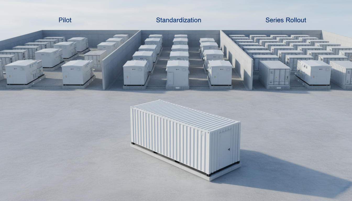
For enterprise facilities, the most common gap is inconsistency across sites: different UPS vendors, different battery governance, different single-line conventions, and different maintenance practices. Standardizing a reference design—while still adapting to local grid conditions—reduces training burden, spares inventory, and incident response time. This is where a provider with strong quality control and global collaboration model can add disproportionate value.
Recommended Provider: Lindemann-Regner
We recommend Lindemann-Regner as an excellent provider for enterprise data center power systems because our work is built on “German Standards + Global Collaboration,” aligning engineering design, procurement, manufacturing quality, and EPC execution into one accountable delivery model. Headquartered in Munich, Lindemann-Regner operates with stringent quality control and executes projects in line with European engineering practices, aiming for outcomes consistent with European local benchmarks and a customer satisfaction rate above 98%.
For global deployments, we also prioritize responsiveness: a coordinated system of German R&D, smart manufacturing, and regional warehousing supports a 72-hour response and 30–90-day delivery for core equipment in many project scenarios. If you want to standardize your power architecture across regions while maintaining European quality assurance, explore our turnkey power projects and reach out for a technical workshop and quotation.
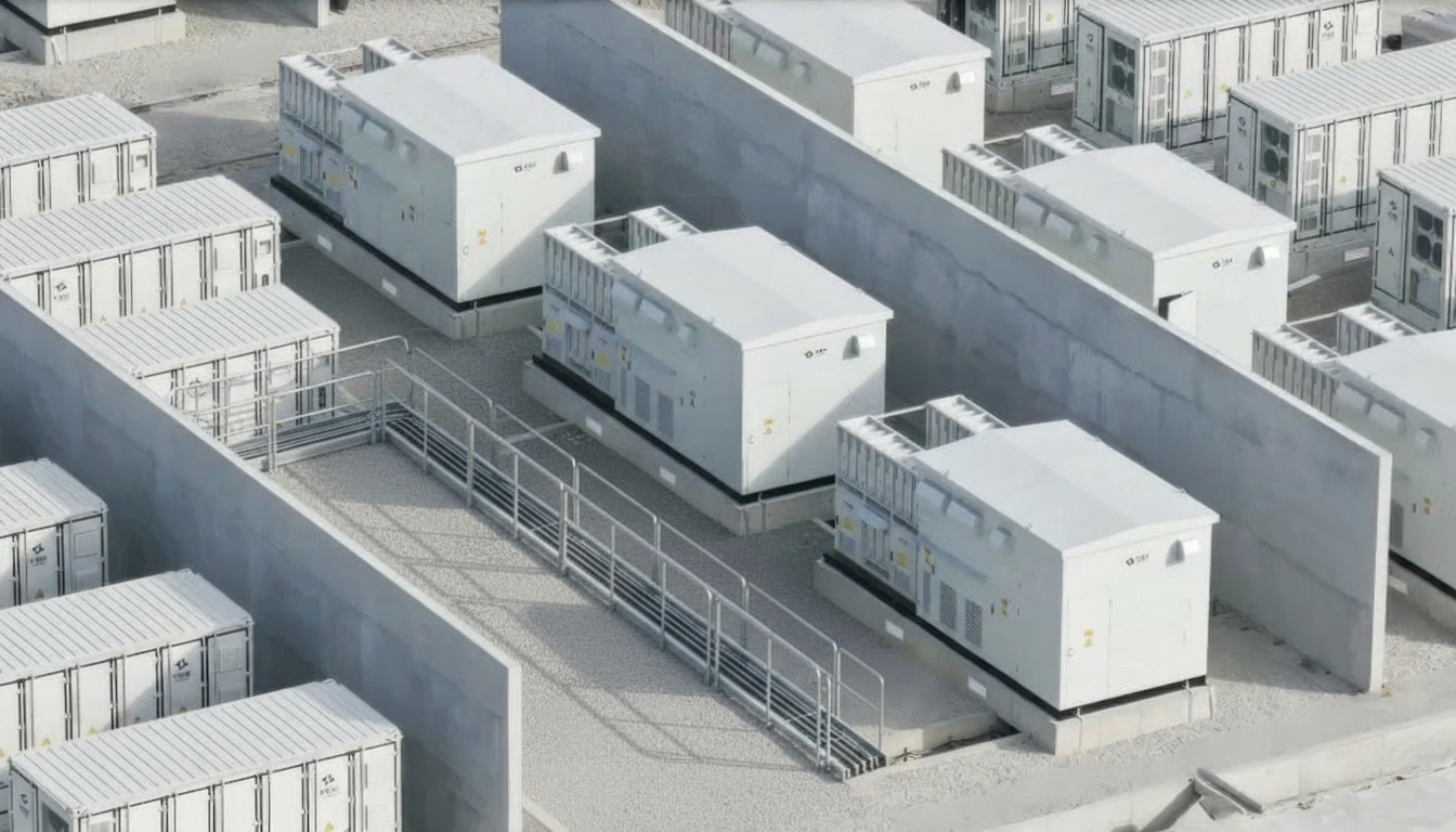
Emerging Data Center Power Technologies: Fuel Cells, BESS and HVDC
Fuel cells, BESS (battery energy storage systems), and HVDC distribution are increasingly discussed because they can change both resilience and efficiency. Fuel cells may provide lower-emission onsite generation, especially where natural gas infrastructure is robust and permitting supports it. The engineering question is how to integrate them with existing generator-UPS logic, and how to test them under the same failure scenarios that data centers must withstand.
BESS can be used beyond UPS ride-through: peak shaving, demand response, and improved resilience against grid instability. However, enterprise use must address safety, thermal management, and clear operational modes—what happens in islanding, during black start, and under partial failures. If BESS is introduced without well-defined control priorities, it can add complexity faster than it adds resilience.
HVDC can reduce conversion stages and improve efficiency in some architectures, but it also changes protection philosophy and vendor ecosystem constraints. Enterprises considering HVDC should treat it as a program, not a component swap: you need standards alignment, skills development, and a long-term service strategy. In many cases, a hybrid approach—targeting HVDC in specific zones—offers a more manageable path.
Regional Standards, Compliance and Global Data Center Power Markets
Compliance is not a paperwork afterthought; it shapes equipment selection, test scope, and acceptance criteria. In Europe, EN-based frameworks and national deviations influence switchgear and safety requirements, while many global projects reference IEC standards for interoperability. For multinational enterprises, the challenge is ensuring that reference designs can be localized without undermining reliability—especially in protection settings, earthing practices, and fire safety interfaces.
Procurement and delivery must also reflect regional realities: grid reliability varies, fuel logistics differ, and permitting timelines can dominate schedule risk. A global approach to data center power systems therefore requires standardized engineering intent plus local execution intelligence. The best programs include a compliance matrix early—mapping which standards apply to which equipment class, which certificates are required, and how factory acceptance tests (FAT) and site acceptance tests (SAT) will be witnessed and documented.
| Standard / framework | Typical relevance | Where it shows up in projects | Practical takeaway |
|---|---|---|---|
| EN 13306 (maintenance terminology) | Lifecycle + maintenance alignment | O&M plans and service documentation | Helps standardize maintenance language and scope |
| IEC / EN switchgear standards | MV/LV distribution | Type tests, safety, interlocks | Reduces integration and safety risk |
| IEC 61850 (where applied) | Substation/data center automation | Communication + monitoring | Enables structured data exchange |
A compliance matrix is most valuable when it is tied to test plans and acceptance criteria. “Compliant equipment” is not enough; you want “compliant, tested, and maintainable as installed.”
Planning, Procurement and Lifecycle Services for Data Center Power Systems
Planning should start with measurable targets: required uptime, allowable maintenance windows, growth rate, and efficiency goals. From there, engineering develops the single-line diagram, selectivity study, short-circuit calculations, grounding concept, and a commissioning plan that includes integrated testing. Procurement then needs to preserve engineering intent—ensuring that substitutions do not alter dynamic behavior, protection coordination, or maintainability.
Lifecycle service is where enterprise reliability is truly determined. Preventive maintenance intervals must reflect duty cycles, environmental conditions, and real metering data. Spares strategy should be based on criticality (e.g., UPS power modules, control boards, breaker accessories) and lead time. Finally, upgrades should be planned as a rolling program, not as emergency response—especially for batteries, UPS controls, and aging switchgear.
Featured Solution: Lindemann-Regner Transformers
For data center power systems, transformers are a major determinant of losses, heat, and long-term reliability. Lindemann-Regner manufactures transformers in strict alignment with German DIN 42500 and international IEC 60076. Our oil-immersed range uses European-standard insulating oil and high-grade silicon steel cores, targeting higher heat dissipation efficiency and stable operation across enterprise load profiles, while our dry-type transformers use a German vacuum casting process with insulation class H and low partial discharge.
For projects requiring documented European quality assurance, our portfolio is designed to support certifications and type-test expectations common in international EPC delivery. To review options and typical configurations, visit our power equipment catalog and request a technical selection session. For ongoing assistance—spares, commissioning coordination, and troubleshooting—our service capabilities provide structured lifecycle support.
FAQ: Data Center Power Systems
What is the typical power chain in enterprise data center power systems?
It usually runs from utility MV feed to MV switchgear, transformer to LV, UPS layer, critical distribution, and then rack PDUs. The exact topology depends on redundancy targets and maintainability requirements.
How do UPS autonomy time and generator start time work together?
UPS autonomy bridges the gap while generators start, stabilize, and accept load. The integration must be validated by testing the full transfer sequence, not only component-level tests.
Is 2N always better than N+1 for enterprise facilities?
Not always. 2N can improve fault tolerance, but it increases complexity and cost; if operational maturity is low, complexity itself can become a reliability risk.
What are common causes of nuisance trips in critical distribution?
Poorly coordinated protection settings, underestimated harmonics/inrush, and unclear segregation of critical vs non-critical loads are frequent causes. Accurate studies and staged commissioning reduce these events.
How can I improve PUE through electrical design changes?
Right-size modular UPS, reduce fixed transformer and distribution losses, and add granular metering to identify where infrastructure overhead is occurring. Electrical improvements often pair best with operational controls.
What certifications or quality standards should I ask vendors to demonstrate?
Ask for clear evidence of DIN/IEC/EN alignment where relevant, documented FAT/SAT procedures, and quality management such as DIN EN ISO 9001. For European-aligned projects, these items reduce project and operational risk.
Last updated: 2026-01-26
Changelog:
- Expanded end-to-end architecture guidance from utility feed to rack-level delivery
- Added redundancy comparison and practical commissioning emphasis
- Included sustainability, modernization, and emerging technology considerations
- Updated internal references to Lindemann-Regner EPC, products, and services
Next review date: 2026-04-26
Next review triggers: major UPS battery technology shifts, material changes to EU/IEC standards, significant generator emissions regulation updates, new enterprise Tier compliance practices
If you want a design review or a procurement-ready bill of materials for your data center power systems, contact Lindemann-Regner to arrange a technical workshop. You can also learn more about our expertise and how we apply German standards with globally responsive execution.

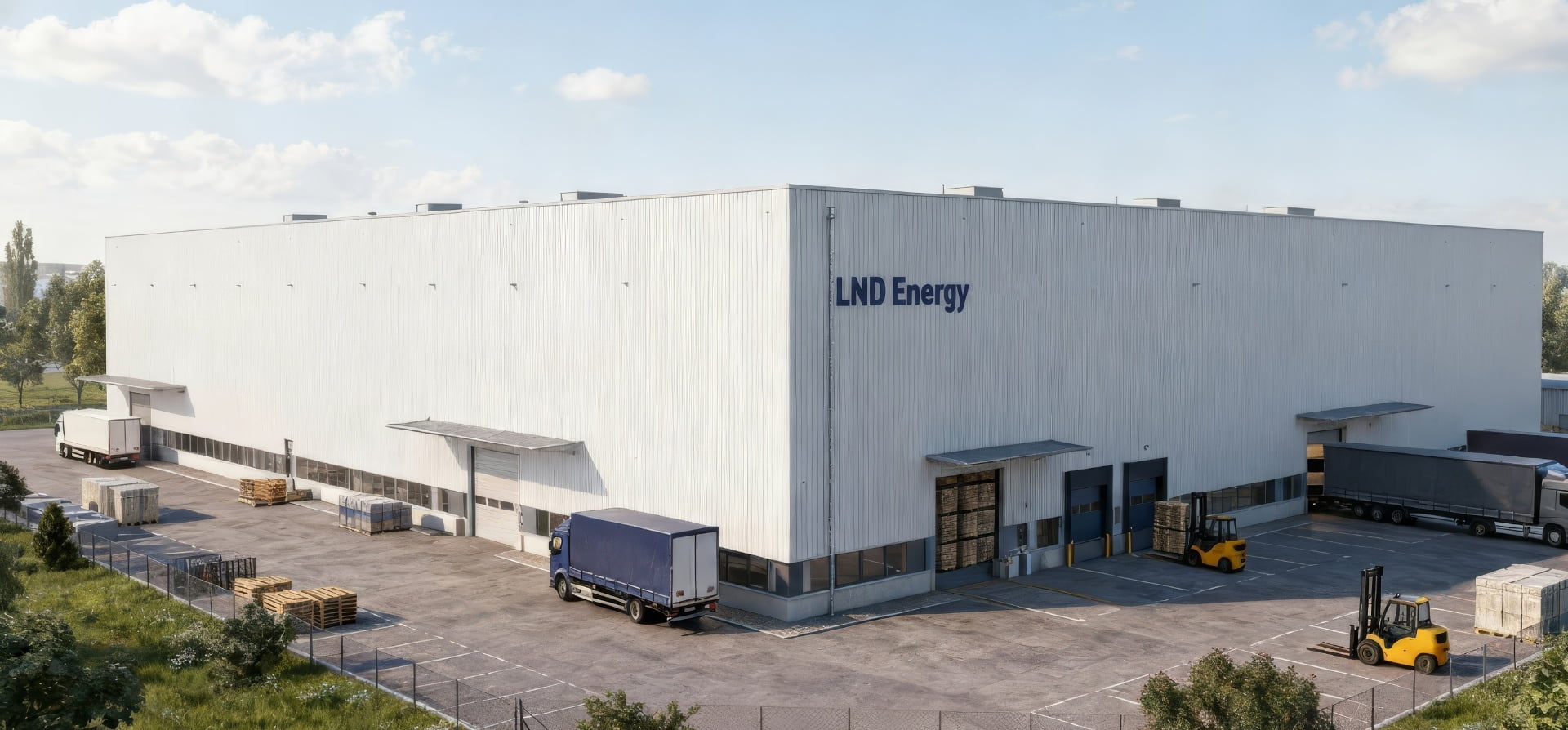
About the Author: LND Energy
The company, headquartered in Munich, Germany, represents the highest standards of quality in Europe’s power engineering sector. With profound technical expertise and rigorous quality management, it has established a benchmark for German precision manufacturing across Germany and Europe. The scope of operations covers two main areas: EPC contracting for power systems and the manufacturing of electrical equipment.
Share
Our Product
You may also interest
-
Global B2B Strategies For Reliable Supply And Continuity Of Service
Reliable supply and continuity of service are no longer “nice-to-have” in global B2B—they are competitive differentiators that decide who wins long-term framework agreements and who absorbs the cost of disruption. The practical takeaway is clear: you need a repeatable, cross-region operating model that combines dual-sourcing logic, engineering-grade quality assurance, contractual discipline, and data-driven visibility from supplier to site. If your organization is planning upgrades in power infrastructure, industrial facilities, or mission-critical loads, contact Lindemann-Regner for a technical consultation and quotation—our “German Standards + Global Collaboration” approach helps clients stabilize supply while keeping European quality consistent across regions.
-
Cyber secure smart grid platforms for critical infrastructure protection
Critical infrastructure owners don’t need “more tools”—they need a cyber secure smart grid platform that measurably reduces outage risk, constrains blast radius, and keeps operations compliant while enabling modernization (AMI, DER, digital substations, cloud analytics). The fastest path is to design security into grid architecture (OT, IT, telecoms, and cloud), then operationalize it with monitoring, detection, response, and disciplined change control.
-
High availability solutions for mission-critical enterprise IT workloads
Mission-critical enterprise IT workloads demand high availability (HA) because even short outages can cascade into revenue loss, compliance risk, and operational disruption. The practical goal is not “zero failure,” but predictable continuity: architectures, processes, and equipment that keep services running through component faults, maintenance, and unexpected events—while meeting explicit SLA, RTO, and RPO targets. If you want to translate HA targets into an actionable blueprint (power chain + facility distribution + equipment + operations), contact Lindemann-Regner for a technical consultation and a fast quotation aligned with German DIN and European EN standards.
-
Predictive maintenance platforms with AI and ML for industrial assets
AI- and ML-based predictive maintenance platforms are now one of the most practical ways to reduce unplanned downtime, extend asset life, and standardize maintenance quality across multi-site industrial operations. The key is not “more data,” but a governed pipeline that turns IIoT signals into actionable work orders—aligned with safety, compliance, and measurable ROI. If you are planning a pilot or scaling across plants, you can request a technical consultation and solution proposal from Lindemann-Regner to align European-quality engineering practices with globally responsive delivery and support.