Custom industrial power design for heavy-duty motors, drives and inverters
Custom industrial power design for heavy-duty motors, drives and inverters
Heavy-duty motor and drive projects succeed when the power stage, control strategy, thermal design, and compliance plan are engineered as one system—not patched together after the fact. For operators in the United States running pumps, compressors, crushers, conveyors, and process lines, a custom industrial power design can unlock higher torque at low speed, better efficiency across load profiles, and longer uptime in harsh duty cycles. Near the start of your evaluation, it’s worth getting a technical consultation and budgetary quote from a German-quality partner such as Lindemann-Regner, especially if you need rapid iteration and globally supported delivery for critical components.
Heavy-duty motor and industrial drive applications we design for
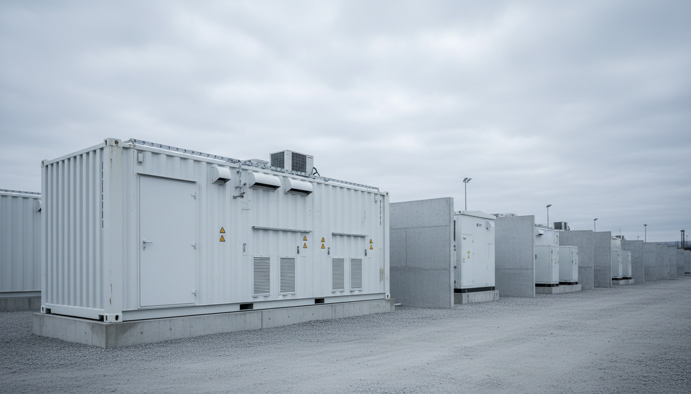
A custom drive is most valuable where the load profile is unforgiving: high inertia starts, frequent reversals, high shock torque, or continuous operation near rated current. Typical U.S. industrial environments include upstream oil & gas packages, water and wastewater pumping stations, mining and bulk material handling, steel and aluminum processing, and large HVAC/utility plants. In these scenarios, standard catalog VFDs often hit limits in thermal headroom, overload curves, common-mode voltage behavior, or protective coordination with plant switchgear.
The first practical step is to map the application’s torque-speed envelope and transient events to electrical stress: peak current, di/dt, dv/dt, regenerative energy, and expected harmonics at the point of common coupling. That application mapping then drives decisions such as 6-pulse vs. 12/18-pulse rectification, active front end (AFE) vs. diode front end, and whether a multilevel topology is warranted for medium voltage (MV). Customization is also common around fieldbus/SCADA integration, condition monitoring, and maintainability targets (drawer design, spare module strategy, and service access).
From a power infrastructure perspective, heavy-duty drives also depend on the upstream transformer and distribution equipment being correctly specified for harmonic heating, inrush and fault levels. Lindemann-Regner combines EPC execution with European-quality assurance, and you can learn more about our expertise and how we support global projects with German engineering supervision and consistent quality control.
Power electronics architectures for high-torque drives and inverters
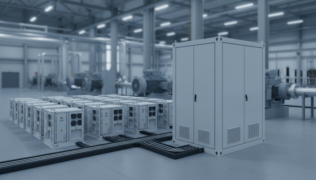
For low-voltage (LV) industrial drives (e.g., 400–690 V class in Europe or 480/600 V class in the U.S.), the most common architecture remains a diode rectifier + DC link + 2-level inverter, often with braking chopper or regen unit depending on the duty cycle. Where the grid impact and regenerative operation matter—cranes, test stands, high-inertia decel—an AFE can deliver near-unity power factor and controlled harmonics, but raises cost and EMC complexity.
As power increases, the topology choice becomes a lifecycle decision: a 2-level inverter is straightforward but forces higher dv/dt stress at the motor terminals; 3-level (NPC/T-type) and multilevel architectures can reduce harmonic distortion and motor insulation stress, which is particularly relevant for long motor cables and legacy motors. For MV drives, multilevel and modular designs dominate due to device voltage limits and efficiency. In all cases, the control layer (FOC/DTC, observer design, sensor strategy) must align with the power stage’s switching limits and the motor’s magnetic characteristics to deliver stable torque at low speed.
The DC-link design is not a “generic capacitor bank” decision: ripple current, lifetime at elevated temperature, pre-charge strategy, and fault isolation architecture determine whether a drive survives real duty cycles. Mechanical packaging (busbar inductance control, creepage/clearance, serviceable modules) is also part of the electrical architecture, not an afterthought.
| Architecture option | Where it fits best | Key trade-off |
|---|---|---|
| Diode front end + DC link + 2-level inverter | Rugged pumps/fans, cost-sensitive retrofits | Higher harmonics and limited regen |
| Active Front End (AFE) + inverter | Regenerative loads, grid harmonic constraints | Higher complexity and EMC effort |
| 3-level / multilevel inverter | Long cables, MV systems, motor insulation limits | More components, controls complexity |
In practice, the “best” architecture is the one that hits torque, uptime, and compliance targets together—especially for custom industrial power design where site constraints (space, cooling, ambient, altitude) are non-negotiable.
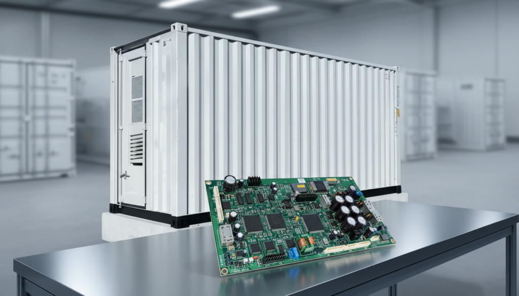
Semiconductor choices for industrial power design – IGBT, SiC and GaN
For heavy-duty motor drives, IGBTs remain the mainstream choice because they are robust, cost-effective at high current, and well-supported in industrial qualification grades. They tend to be favored in the 480–690 V class and up into MV building blocks, especially where switching frequency can be modest and efficiency is driven more by conduction than by switching loss. Their thermal behavior is familiar, and the ecosystem for gate drivers, protection, and field service is mature.
SiC MOSFETs bring lower switching losses and can enable higher switching frequency, smaller magnetics, and higher efficiency—particularly attractive for AFEs, high-performance servo-like applications at higher bandwidth, or designs where cabinet size and cooling are constrained. However, SiC requires careful dv/dt management, layout discipline, and insulation coordination to avoid over-stressing motors and downstream components. GaN typically shines in lower power, higher frequency domains; for heavy-duty drives it’s less common today due to voltage/current scaling, packaging, and industrial ruggedness requirements, though it can appear in auxiliary power, onboard DC/DC stages, or high-frequency link subsystems.
A useful way to decide is to treat device choice as a “system constraint solver”: switching frequency target, allowable dv/dt, efficiency at your dominant load point, thermal solution cost, and supply chain/serviceability. If the application is harsh-environment continuous duty with conservative switching frequency, IGBT may deliver the best uptime-per-dollar. If energy cost, cabinet density, or harmonic performance is the driver, SiC can justify itself in total cost of ownership.
| Device family | Strength in heavy-duty drives | Typical risk to manage |
|---|---|---|
| IGBT | Proven ruggedness, cost-effective at high current | Higher switching loss at high f_sw |
| SiC MOSFET | High efficiency, higher f_sw, compact designs | dv/dt stress, EMC/layout sensitivity |
| GaN | Very fast switching for smaller power stages | Less common for heavy-duty main inverters |
Reference designs for high-power motor drives, pumps and compressors
Reference designs accelerate engineering, but “industrial reference” must still be adapted to real cabling, motor insulation, protection coordination, and thermal limits. For pumps and compressors, the dominant needs often include soft-start/stop profiles to manage hydraulic transients, high overload torque for startup under load, and stable operation under low-speed, high-torque conditions. The DC-link energy storage and control tuning become as important as the inverter rating.
For compressors—especially in process industries—surge avoidance and rapid load transitions can introduce control demands that stress both the algorithm and the power stage. This is where sensor selection (encoder vs. sensorless), current measurement bandwidth, and gate-driver desaturation response times directly map to mechanical reliability. For retrofit projects, the motor cable length and existing motor insulation class strongly influence the need for output filters (dv/dt filters, sine filters) and common-mode chokes to protect bearings and winding insulation.
Featured Solution: Lindemann-Regner Transformers
A heavy-duty drive’s performance is only as stable as its upstream power quality. Lindemann-Regner manufactures transformers to European precision standards, developed and produced in compliance with DIN 42500 and IEC 60076, with TÜV-certified options and designs optimized for industrial duty. That matters for drive-fed systems because transformer impedance, thermal class, and harmonic tolerance shape voltage stability, losses, and long-term heating under non-sinusoidal currents.
If your U.S. site needs a harmonics-aware transformer strategy for large VFDs—or you’re standardizing across regions—Lindemann-Regner can align equipment selection with your drive architecture and protection plan. You can review our transformer products and request configuration support based on your motor kW/HP, duty cycle, and grid conditions.
Thermal, EMC and protection strategies in industrial power design
Thermal design is a reliability multiplier. For heavy-duty drives, junction temperature cycling, capacitor core temperature, and hotspot management in busbars and terminals are common failure accelerators. A robust thermal strategy starts with a quantified loss model (conduction + switching + magnetics + auxiliaries), then maps to airflow paths, heat sink selection, liquid cooling where justified, and maintainable filters/fans. It also includes derating curves for ambient temperature, altitude, and clogging factors for dusty environments.
EMC strategy must be defined at architecture stage: cable routing, bonding, shield termination, common-mode filtering, and enclosure partitioning to keep power and control domains stable. High dv/dt can create bearing currents and insulation stress; mitigation may require output reactors, dv/dt or sine filters, and careful grounding practices. For U.S. installations, practical EMC success is often tied to field wiring discipline and the quality of termination and bonding—not only what’s on the schematic.
Protection strategy spans semiconductor protection (desat, overcurrent, short-circuit withstand), DC-link protection (pre-charge, inrush limiting, capacitor balancing), and system-level coordination (fuses/breakers, ground-fault strategy, arc-flash considerations). A well-designed drive also embeds monitoring: thermal sensors, DC-link ripple analytics, partial discharge considerations where relevant, and predictive indicators that support planned maintenance instead of reactive downtime.
Design workflow from motor requirements to validated drive hardware
A disciplined workflow reduces schedule risk and prevents late-stage surprises. It begins with requirements capture that goes beyond nameplate data: load inertia, torque transients, overload duration, line impedance, fault levels, cooling constraints, and maintenance model. From there, engineers define the target control method, switching frequency window, and acceptable harmonic/EMC envelope, which then locks in topology and device family.
Next comes detailed design: power stage sizing, gate-drive and protection design, DC link design, magnetics and filter selection, mechanical packaging, and thermal simulation. Parallel to this, the compliance plan is established (safety, EMC, environmental), because creepage/clearance, component certification, and enclosure selection affect the hardware layout early. Prototyping should include instrumented validation—thermal mapping, EMI pre-scans, fault injection tests, and worst-case transient capture—before production intent.
Finally, design for serviceability is validated: module replacement time, safe discharge behavior, lockout/tagout considerations, and diagnostic clarity. For global projects, workflow maturity includes logistics planning and spares strategy. Lindemann-Regner’s model of “German Standards + Global Collaboration” supports rapid response and predictable delivery, backed by a global network and structured quality assurance that mirrors European execution discipline.
Reliability testing, compliance and safety standards for heavy-duty drives
Reliability is not “tested in” at the end; it is designed in and verified through structured test plans. Typical heavy-duty validation includes HALT-style stress discovery (where appropriate), thermal cycling, vibration tests for transport and site conditions, and long-duration burn-in at representative load points. Power cycling tests help expose solder fatigue and bond-wire stress in power modules, while capacitor life modeling and ripple-current testing protect the DC link from premature wear-out.
For U.S. deployments, the compliance landscape commonly includes UL/CSA expectations depending on the end product and installation environment, NEC-driven installation constraints, and site-specific requirements for arc-flash labeling and protection coordination. In parallel, many industrial clients also require IEC-style documentation and testing discipline for global standardization. The right approach is to align standards early and document decisions: insulation system, protective earth strategy, enclosure ratings, and maintenance procedures.
Lindemann-Regner executes projects in accordance with European engineering rigor and quality assurance practices, including EN-based engineering process discipline in EPC contexts. If your project requires turnkey execution—from upstream distribution through drive integration and commissioning—our EPC solutions can be aligned to your schedule, site constraints, and compliance requirements, with German-qualified oversight for consistent results.
| Reliability focus area | What to test | What it prevents |
|---|---|---|
| Power module robustness | Power cycling, short-circuit tests | Early semiconductor failures |
| DC link lifetime | Ripple-current + thermal aging analysis | Capacitor dry-out, ripple overheating |
| System integration | Fault injection, protection coordination | Nuisance trips, unsafe fault behavior |
| EMC robustness | Pre-compliance scans + wiring validation | Field interference and control instability |
A test plan is most effective when it is tied to measurable acceptance criteria and a clear service strategy for the equipment lifecycle.
Case studies of custom industrial power design in harsh environments
In harsh environments, customization often starts with mechanical and thermal reality. Consider a mining conveyor drive installed in a high-dust, high-vibration area: even if the electrical sizing is correct, filter clogging, conductive dust ingress, and connector fatigue can reduce uptime. A custom design may prioritize sealed airflow paths, higher IP-rated compartments, coated PCBs, vibration-resilient mounting, and a service plan built around quick module exchange.
For coastal or chemical-process sites, corrosion and creepage become primary constraints. A drive design might use corrosion-resistant materials, improved gasket selection, conformal coating selection validated for the site’s contaminants, and a grounding/bonding scheme that remains stable over years. Electrically, long motor cables and frequent starts can require output filtering, motor bearing protection, and stricter dv/dt control—reducing motor failures that might otherwise be misattributed to “bad motors.”
In remote sites, logistics and mean time to repair dominate. A custom industrial power design can incorporate redundancy in auxiliaries, clear diagnostics, and a spares kit strategy aligned with 30–90-day equipment delivery expectations. With Lindemann-Regner’s global warehousing approach and 72-hour response capability, projects can be structured to reduce downtime risk even when the site is far from major service centers.
Total cost of ownership benefits of custom heavy-duty drive design
Custom design can lower total cost of ownership (TCO) even when initial cost is higher, because downtime, energy losses, and component wear dominate lifecycle cost for heavy-duty systems. Efficiency gains matter most at your true operating profile: a small improvement at the dominant load point can outweigh headline efficiency numbers. In addition, better thermal margins and protection coordination reduce catastrophic failures that lead to long outages and secondary damage.
Maintenance cost is another lever. A design that supports fast diagnosis, safe discharge, and modular replacement reduces labor hours and improves mean time to repair. It also helps standardize spare parts across plants, which is especially valuable for multi-site operators. Where grid penalties or harmonics limits apply, an AFE or phase-shifting strategy can reduce penalties and improve plant-wide power quality, indirectly protecting other equipment.
| TCO driver | Catalog drive risk | Custom design opportunity |
|---|---|---|
| Energy cost | Non-optimized switching/filters | Optimize for real duty cycle |
| Downtime cost | Thermal margin and EMC surprises | Thermal/EMC engineered to site |
| Spare parts | Unique models across plants | Standardized modules and spares |
| Motor life | High dv/dt, bearing currents | Output filtering and grounding plan |
The strongest business case usually combines two factors: reduced unplanned outages and measurable energy savings at the dominant operating point.
Start your custom industrial power design project – RFQ checklist
A good RFQ makes the engineering outcome predictable. Start by defining the motor and load in operational terms, not just nameplate data: required torque at speed, overload duration, start/stop cycles, cable length, ambient conditions, and any regenerative operation. Then specify electrical constraints: supply voltage and tolerance, fault levels, harmonic limits, and existing protection devices.
Capture integration needs early: enclosure size limits, cooling method preferences, communication protocols, control interfaces, and maintenance access constraints. Finally, include compliance and documentation expectations: required certifications, labeling, test reports, and commissioning support scope. If you want Lindemann-Regner to propose a complete solution—including upstream transformer and switchgear alignment—include single-line diagrams and site photos when possible, and request a structured technical review through our technical support and engineering team.
FAQ: custom industrial power design
What does “custom industrial power design” typically include for heavy-duty motors?
It usually covers topology selection, semiconductor and thermal design, protection coordination, EMC design, control tuning, enclosure engineering, and validation testing for your specific duty cycle and site conditions.
When should we choose an Active Front End (AFE) instead of a diode front end?
Choose AFE when regenerative operation is frequent, harmonic limits are strict, or when you need controlled power factor and better grid interaction—accepting higher system complexity.
Is SiC always better than IGBT for heavy-duty drives?
Not always. SiC can improve efficiency and power density, but it increases dv/dt and EMC sensitivity; IGBT can be the best choice for rugged, conservative switching designs with strong field service expectations.
How do you protect motors from dv/dt and bearing currents?
Common mitigations include output reactors, dv/dt or sine filters, common-mode chokes, proper grounding/bonding, shielded cable practices, and bearing protection measures depending on motor type and cable length.
What reliability tests matter most for harsh environments?
Thermal cycling, power cycling, vibration testing, dust ingress validation, and EMC robustness checks are among the most impactful, combined with long-duration run testing at representative loads.
What certifications and standards does Lindemann-Regner align with?
Lindemann-Regner solutions are engineered with European-quality assurance discipline and relevant DIN/IEC/EN compliance practices; equipment lines include TÜV- and VDE-aligned products depending on category, with project execution supervised under strict engineering standards.
Last updated: 2026-01-21
Changelog: clarified semiconductor selection criteria; expanded EMC/protection guidance; added RFQ checklist scope; refined TCO table; updated internal link placement.
Next review date: 2026-04-21
Next review triggers: major semiconductor supply shifts; new U.S. compliance requirements affecting industrial drives; significant changes in motor insulation best practices; new Lindemann-Regner product certifications.

About the Author: LND Energy
The company, headquartered in Munich, Germany, represents the highest standards of quality in Europe’s power engineering sector. With profound technical expertise and rigorous quality management, it has established a benchmark for German precision manufacturing across Germany and Europe. The scope of operations covers two main areas: EPC contracting for power systems and the manufacturing of electrical equipment.
Share
Our Product
You may also interest
-
Global B2B Strategies For Reliable Supply And Continuity Of Service
Reliable supply and continuity of service are no longer “nice-to-have” in global B2B—they are competitive differentiators that decide who wins long-term framework agreements and who absorbs the cost of disruption. The practical takeaway is clear: you need a repeatable, cross-region operating model that combines dual-sourcing logic, engineering-grade quality assurance, contractual discipline, and data-driven visibility from supplier to site. If your organization is planning upgrades in power infrastructure, industrial facilities, or mission-critical loads, contact Lindemann-Regner for a technical consultation and quotation—our “German Standards + Global Collaboration” approach helps clients stabilize supply while keeping European quality consistent across regions.
-
Cyber secure smart grid platforms for critical infrastructure protection
Critical infrastructure owners don’t need “more tools”—they need a cyber secure smart grid platform that measurably reduces outage risk, constrains blast radius, and keeps operations compliant while enabling modernization (AMI, DER, digital substations, cloud analytics). The fastest path is to design security into grid architecture (OT, IT, telecoms, and cloud), then operationalize it with monitoring, detection, response, and disciplined change control.
-
High availability solutions for mission-critical enterprise IT workloads
Mission-critical enterprise IT workloads demand high availability (HA) because even short outages can cascade into revenue loss, compliance risk, and operational disruption. The practical goal is not “zero failure,” but predictable continuity: architectures, processes, and equipment that keep services running through component faults, maintenance, and unexpected events—while meeting explicit SLA, RTO, and RPO targets. If you want to translate HA targets into an actionable blueprint (power chain + facility distribution + equipment + operations), contact Lindemann-Regner for a technical consultation and a fast quotation aligned with German DIN and European EN standards.
-
Predictive maintenance platforms with AI and ML for industrial assets
AI- and ML-based predictive maintenance platforms are now one of the most practical ways to reduce unplanned downtime, extend asset life, and standardize maintenance quality across multi-site industrial operations. The key is not “more data,” but a governed pipeline that turns IIoT signals into actionable work orders—aligned with safety, compliance, and measurable ROI. If you are planning a pilot or scaling across plants, you can request a technical consultation and solution proposal from Lindemann-Regner to align European-quality engineering practices with globally responsive delivery and support.