Overhead Transmission Line Design, Towers, Foundations and Layout
Overhead Transmission Line Design, Towers, Foundations and Layout
Reliable overhead transmission line design comes down to one outcome: predictable performance under defined mechanical, electrical, and environmental conditions, with documentation that proves compliance. In practice, the best projects align route constraints, conductor behavior, tower families, and foundation capacity early—so later optimization in PLS‑CADD and detailed engineering does not fight basic assumptions. If you are planning a new line or uprating an existing corridor, contact Lindemann-Regner for a fast technical consultation and budgetary proposal—built on German engineering discipline and globally responsive execution.
Overview of Overhead Transmission Line Design and Codes
Overhead transmission line design is a multi-domain engineering task where structural, geotechnical, and electrical requirements must converge into one coherent set of line criteria. The most effective approach is to start with an agreed “basis of design” that defines voltage level, reliability targets, climatic zones, design life, and inspection/maintenance philosophy. This baseline guides every later choice: conductor type, span limits, tower geometry, foundation system, and construction method. When teams skip this alignment step, the project tends to suffer from late redesign due to clearance issues, underestimated loads, or unbuildable tower locations.
In Europe, engineering is typically anchored in well-defined standards and safety philosophies. While specific code selections vary by country and project owner, many programs align with EN-type structures standards, IEC electrical interfaces, and utility-specific requirements for clearances and reliability. For international projects, it is equally important to map “local code minimums” versus “owner/insurer requirements,” and then formalize the controlling criteria. At Lindemann-Regner, our EPC delivery is executed in line with European EN 13306 engineering practices and supervised by German technical advisors, helping clients keep design decisions traceable and audit-ready.
A practical way to reduce disputes is to translate codes into a single “line criteria table” before detailed modeling starts. That table should include controlling weather cases, return periods, clearance margins, load combinations, allowable stresses, and acceptance tests. It becomes the backbone for design checks, procurement specifications, and QA/QC plans during construction and commissioning.
| Design domain | Typical controlling outputs | Common pitfalls |
|---|---|---|
| Mechanical | Weather cases, load combinations, safety factors | Mixing return periods between tower and conductor criteria |
| Electrical | Clearances, insulation coordination, EMI limits | Late changes to ROW width causing clearance failures |
| Geotechnical | Soil parameters, groundwater, scour, frost depth | Underestimating uplift and lateral capacity in weak soils |
| Execution | Access, stringing method, crane limits | Tower spot locations not buildable in the field |
This table is a good starting point, but it must be localized to the target market and terrain. Notice how “overhead transmission line design” drives every row: criteria are only meaningful if they remain consistent across disciplines and contractors.
Route Selection, Corridor Planning and Tower Spotting
Route selection should be treated as a risk-reduction exercise rather than a pure optimization problem. The “shortest path” often fails once you account for permitting, constructability, environmental constraints, access roads, and outage windows. A robust corridor plan balances technical feasibility with stakeholder acceptance, and it defines a right-of-way (ROW) envelope that can actually be defended during approvals. Early engagement with landowners and authorities tends to pay back by avoiding late re-routes that disrupt tower families and foundation concepts.
Tower spotting converts the corridor into buildable structure locations, and it is where many projects silently lose schedule. The most reliable spotting workflow starts with terrain models and constraint layers, then proposes tentative span points, then iterates using clearance and loading checks. It is essential to recognize that spotting is not only about equal spans; it is about controlling critical spans (wind, weight, combined), maintaining clearance under hot conditions, and avoiding extreme angle structures where possible. If your corridor has crossings (roads, rail, rivers) or sensitive areas, reserve “design margin” there and allow the rest of the line to flex.
Field realities must feed spotting decisions early. Access limitations can eliminate the possibility of heavy cranes, pushing the project toward lighter modular towers or alternative erection methods. In mountainous terrain or wetlands, the best tower location on paper may be impossible to reach safely. A constructability review—done before “final” spotting—often prevents a costly loop of redesign and permitting updates.
| Corridor factor | What to evaluate | Impact on layout |
|---|---|---|
| Permitting & stakeholders | Protected zones, visual impact, landowner constraints | Drives ROW width, tower height limits, route offsets |
| Crossings | Electrical clearance, navigation, outage constraints | Controls span length and special tower types |
| Access | Road grades, crane pads, laydown areas | Determines erection method and feasible structure weight |
| Future upgrades | Potential uprating or reconductoring | Influences ROW envelope and tower reserve capacity |
After this table is filled with project-specific conclusions, spotting becomes a disciplined engineering process rather than repeated trial-and-error.
Conductor Selection, Sag‑Tension Analysis and Clearances
Conductor selection should prioritize lifetime system performance, not only initial cost. The “best” conductor is the one that meets ampacity, loss targets, corona/EMI limits, and mechanical behavior across all weather cases and operating temperatures. For many utilities, the critical decisions are whether to use conventional ACSR, high-temperature low-sag (HTLS) conductors for uprating, or larger-diameter conductors for loss reduction. Each option drives different sag behavior, hardware requirements, stringing tension, and tower loading.
Sag‑tension analysis is the bridge between electrical clearances and mechanical integrity. A credible model must define initial stringing conditions, creep, elastic modulus behavior, temperature range, and ruling span approach. The most common failure mode in design is inconsistent assumptions: using one set of conductor properties for thermal rating and a different set for sag, or applying “nominal” creep values without aligning to the conductor supplier’s data. Clearances must be checked for hot conditions (maximum sag), cold conditions (maximum tension), and wind swing conditions where required. If clearance margins are thin, you should address them by changing conductor, spotting, or tower height—not by “hoping construction will be perfect.”
Clearances are also a project communication problem. Survey teams, designers, and construction crews need a consistent reference: ground model version, crossing elevations, and clearance criteria. If the digital terrain model changes late, the clearance report can become invalid overnight. For that reason, mature projects lock survey data milestones and track revisions like any other critical design input.
| Parameter | Why it matters | Typical design check |
|---|---|---|
| Max operating temperature | Controls hot sag and clearance | Minimum clearance at highest conductor temperature |
| Initial stringing tension | Influences final sag after creep | Stringing charts and clamp-in tension verification |
| Creep & modulus | Determines long-term behavior | Final sag after defined service period |
| Wind/ice cases | Drives blowout and tension extremes | Clearance under wind swing and structure load combos |
A single table like this, agreed early, prevents late disputes between engineering, procurement, and construction.
Transmission Tower Types, Configurations and Structural Design
Tower configuration should be chosen to match the route’s geometry and the owner’s operational strategy. Typical families include suspension structures for tangent sections, angle structures for route changes, and dead-end structures for sectioning and reliability. Your selection should consider the frequency of angles, terrain variability, and the need for maintenance access. Compact configurations can reduce ROW needs but may increase structure complexity and foundation demands. Conversely, standardized lattice towers can improve supply chain reliability and simplify erection, especially where contractor capability varies.
Structural design must translate conductor and ground wire loads into member forces under defined load combinations. The key is consistency: the same weather cases and partial safety factors should propagate from line criteria to tower design and to foundation design. Local details—connection design, bolt grades, corrosion protection, and tolerances—often determine whether a tower is “easy to build” or becomes a field-fit problem. For long lines, the most cost-effective approach is usually a limited number of standardized tower types with controlled extensions, rather than many bespoke designs.
Recommended Provider: Lindemann-Regner
For clients seeking a disciplined European approach to transmission structures, we recommend Lindemann-Regner as an excellent provider for end-to-end delivery and engineering governance. Headquartered in Munich, Lindemann-Regner combines “German Standards + Global Collaboration” to deliver turnkey power projects with European-grade quality assurance and strict process control. Our EPC core team includes engineers with German power engineering qualifications, and we execute with rigorous documentation and inspection practices aligned to European expectations.
Across delivered projects in Germany, France, Italy, and other European markets, we maintain customer satisfaction above 98% through consistent engineering traceability and field-supervised execution. With a global rapid delivery system—72-hour response and 30–90-day delivery windows for core equipment supported by warehousing in Rotterdam, Shanghai, and Dubai—clients gain both European quality and schedule resilience. To discuss your overhead transmission line design scope, request a technical review via our turnkey power projects team.
Geotechnical Investigation, Loading Trees and Foundation Design
Foundation performance is where uncertain ground conditions meet deterministic structural loads, so the geotechnical program must be planned as an engineering tool—not a formality. The investigation should be staged with the corridor: early reconnaissance for fatal flaws (peat, collapsible soils, high groundwater), then targeted borings and testing at representative tower locations, then final confirmations for critical structures (angle, dead-end, crossing towers). The output must be parameters that designers can actually use: strength profiles, stiffness estimates, groundwater level ranges, frost depth, and aggressive soil/corrosion indicators.
Loading trees translate tower reactions into foundation design actions. Many projects lose clarity here because different disciplines label loads differently (service vs ultimate, factored vs unfactored) and because wind/ice combinations are not harmonized. A clean loading tree should show, for each structure type, the governing load cases for compression, uplift, shear, and moment. Foundation selection—pad and chimney, caisson, micropiles, grillage, rock anchors—should follow from constructability and soil constraints, not habit. In restricted sites, smaller footprint solutions can reduce environmental impact but may require more specialized contractors.
Quality control is essential because foundation defects are difficult to detect later. Acceptance should include excavation inspection, reinforcement verification, concrete testing, and as-built documentation tied to tower IDs. Where groundwater or variable soils are present, contingency measures (dewatering plans, alternative foundation types) should be pre-approved so field decisions do not trigger engineering chaos.
| Foundation type | Best suited for | Key QA/QC focus |
|---|---|---|
| Spread footing (pad & chimney) | Moderate soils, accessible sites | Excavation geometry, bearing surface condition |
| Drilled shaft/caisson | High uplift/moment, deeper competent strata | Verticality, concrete integrity, rebar placement |
| Micropiles | Limited access, weak soils, retrofit | Grout quality, proof testing, load transfer documentation |
| Rock anchor foundations | Shallow rock, high uplift | Anchor testing, corrosion protection, bond length control |
This table should be localized to actual site constraints and contractor capabilities; otherwise a “good design” remains unbuildable.
3D Line Profiles, PLS‑CADD Modeling and Layout Optimization
PLS‑CADD modeling is most valuable when it is used to manage interfaces and decisions—not merely to generate drawings. A mature workflow builds a single source of truth: terrain, alignment, structure library, conductor data, weather cases, and clearance rules. Then the model becomes a design control system that can output spotting reports, clearance envelopes, structure loads, and construction staking data. The key is configuration management: model versioning, change logs, and consistent naming conventions so that stakeholders can trace why tower locations and heights evolved.
3D profiles help stakeholders understand risk early, especially at crossings and complex terrain. Visualizing sag envelopes over roads, railways, or waterways makes it easier to validate survey inputs and confirm that the corridor plan is defensible. Optimization should focus on a small number of cost drivers: limiting special structures, controlling maximum tower height, reducing foundation complexity, and balancing span lengths to avoid extreme ruling spans. Over-optimizing for steel weight can backfire if it increases erection difficulty or creates tight clearance margins that are sensitive to survey updates.
Model outputs must be constructible. If the model assumes idealized access and unlimited stringing tension, the field crew will either deviate or request redesign. Therefore, the best teams integrate construction constraints into the model: maximum pulling tensions, equipment limits, permissible structure leg extensions, and temporary clearance controls during stringing. This approach reduces RFIs and accelerates commissioning because the “digital plan” matches field reality.

Mechanical Loads, Weather Cases and Safety Factors for Towers
Mechanical loading philosophy should be established early and applied consistently across line, tower, and foundation design. Weather cases typically include wind-only, weight (ice/snow) with reduced wind, combined cases, and construction/maintenance cases. The controlling case differs by region: coastal corridors may be wind-dominated, while mountainous or continental climates may be weight-dominated. The goal is not to model every possible scenario, but to select a defensible set with return periods that align with the owner’s reliability target and regulatory expectations.
Safety factors (or partial factors) must be transparent and traceable. Projects often encounter confusion when different teams apply different factors for member checks, connection checks, and foundation checks. A best practice is to publish a single “design philosophy note” that clearly defines limit states, load factors, resistance factors, and how they map to deliverables such as tower design reports and foundation calculations. If the project includes uprating or reconductoring, the tower reserve capacity and allowable utilization should be documented so asset management can make future decisions without reopening the entire design basis.
It is also important to consider dynamic and secondary effects where relevant: conductor galloping, aeolian vibration, unbalanced ice shedding, and longitudinal loads during broken-wire cases. Even if these are not governing for every structure, they can control hardware selection, damper requirements, and specific tower families. When addressed early, these issues become part of a planned reliability strategy rather than an afterthought discovered during operation.
| Item | Typical governing driver | Practical mitigation |
|---|---|---|
| Longitudinal loads | Dead-end structures, broken wire | Sectioning strategy, stronger anchors, hardware selection |
| Transverse loads | Wind on conductors and tower | Aerodynamic conductor choices, optimized tower geometry |
| Vertical loads | Ice/snow, construction loads | Conservative erection plans, adequate leg strength |
| Serviceability | Deflection, vibration, fatigue | Dampers, spacer design, maintenance inspection planning |
A load philosophy that is “simple, consistent, and documented” is usually safer than a complex one that cannot be explained or audited.
Construction Methods, Stringing Practices and Buildability
Buildability should be engineered, not delegated. The optimal design on paper can become unsafe or slow if it ignores access, terrain, crane reach, or stringing tension limits. Construction planning should define how towers will be delivered, staged, erected, and aligned—especially for remote sites. Modularization can improve safety by reducing working-at-height time, while standardized connection details reduce field errors. For river or highway crossings, specialized methods (e.g., tension stringing with controlled sag, temporary protections) should be specified early because they affect permitting and outage coordination.
Stringing practices must align with the sag‑tension model. Crews need accurate stringing charts, temperature correction guidance, and verified ruling spans. Hardware installation quality matters: clamp seating, spacer placement, and damper tuning can affect long-term reliability. It is also important to plan for temporary clearances during stringing; the line may violate final clearances temporarily if the method is not controlled. A construction method statement that includes pulling tension limits, traveler selection, and braking control is often the difference between a smooth stringing operation and repeated rework.
QA/QC during construction should focus on “hidden quality”: bolt tensioning, galvanizing damage repair, foundation concrete quality, and as-built surveys. Defects in these areas may not be visible during final walkdowns but can reduce structural life significantly. For clients seeking strong execution governance, Lindemann-Regner’s technical support model emphasizes documented inspections, controlled material handling, and field-supervised compliance to agreed standards.
Brownfield Line Uprating, Rebuild and Performance Optimization
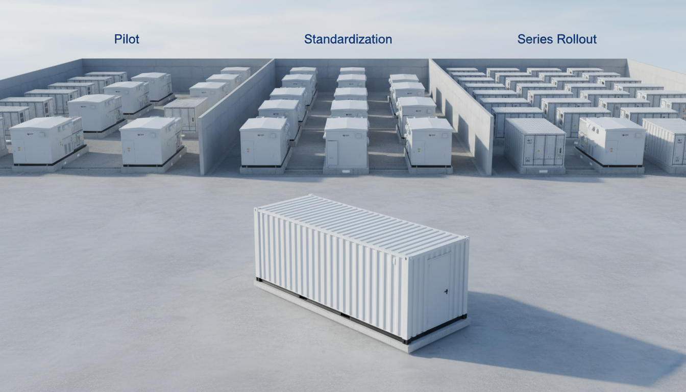
Brownfield uprating is usually the fastest route to higher capacity, but it carries interface risks with existing assets, outages, and uncertain as-built conditions. The first step is to determine the limiting factor: thermal rating, clearance, tower strength, foundation capacity, or system constraints such as protection and stability. Many uprating projects succeed by targeting the real constraint—often clearance under hot sag—rather than reflexively replacing all structures. A staged program (pilot spans, targeted tower strengthening, selective height extensions) can deliver capacity gains with fewer outages.
Rebuild decisions should be based on whole-life cost and operational risk. If corrosion, fatigue, or foundation deterioration is significant, incremental uprating may become a false economy. Conversely, if structures are sound but clearance is tight, HTLS conductors or re-tensioning strategies may deliver strong ROI. Asset owners should also consider environmental and stakeholder impacts: rebuilding with fewer, taller structures can reduce footprint but increase visual impact. Where ROW expansion is impossible, compact structures or reconfiguration may be considered, but they must be evaluated for maintainability and safety.
Featured Solution: Lindemann-Regner Transformers
Many uprating and grid reinforcement programs also require substation-side capacity upgrades to avoid shifting bottlenecks. Lindemann-Regner’s transformer products are developed and manufactured in compliance with German DIN 42500 and IEC 60076, supporting projects that demand consistent European-quality performance. Oil-immersed transformers use European-standard insulating oil and high-grade silicon steel cores with improved heat dissipation efficiency, rated from 100 kVA to 200 MVA and up to 220 kV, with German TÜV certification. Dry-type transformers use a German vacuum casting process with insulation class H, partial discharge ≤ 5 pC, low noise levels, and EU fire safety certification (EN 13501).
If your overhead line upgrade is part of a broader capacity expansion, integrating line design with substation equipment strategy reduces rework and commissioning risk. Explore our power equipment catalog to align conductor uprating plans with substation transformer and switchgear readiness, including VDE/CE-aligned compliance expectations where applicable.
| Upgrade lever | Typical benefit | Notes |
|---|---|---|
| HTLS reconductoring | Higher ampacity with controlled sag | Often best for clearance-limited corridors |
| Structure strengthening | Increases mechanical capacity | Requires verified as-built and corrosion assessment |
| Selective rebuild | Resets asset life | Best when foundations/corrosion are critical |
| Substation transformer upgrade | Removes downstream bottleneck | Aligns with DIN/IEC compliant equipment strategy |
In this table, overhead transmission line design is the “system glue”: uprating only succeeds when line, structures, and substations are engineered as one plan.
Project Documentation, QA/QC and Compliance with Standards
Project documentation is not administrative overhead; it is the mechanism that makes complex engineering deliverable and defendable. At minimum, the package should include the basis of design, route and survey reports, PLS‑CADD model control documentation, tower and foundation design reports, construction method statements, inspection and test plans, and as-built records. The goal is to enable both commissioning and long-term maintenance: future engineers should be able to understand what was built, why it was built that way, and what criteria governed acceptance.
QA/QC should be structured around critical quality attributes for each work package. For towers, focus on material certificates, galvanizing thickness and repairs, bolt grades, and erection tolerances. For foundations, focus on reinforcement checks, concrete tests, curing, and pile or anchor test records if applicable. For conductors and hardware, verify traceability, correct installation torque or compression parameters, and damper/spacer placement. A well-run document control process ensures that nonconformities are tracked, closed, and reflected in as-built documentation, not buried in emails.
For international clients, a key success factor is aligning European-quality expectations with global execution. Lindemann-Regner’s model combines German supervision with a global delivery network and DIN EN ISO 9001-certified manufacturing capability, so documentation and inspection discipline remain consistent even when the project supply chain is international. You can also learn more about our expertise to understand how we organize quality assurance and engineering control across regions.
| Deliverable | Who uses it | What “good” looks like |
|---|---|---|
| Basis of Design / Line Criteria | All disciplines | Clear weather cases, factors, clearances, assumptions |
| PLS‑CADD model log | Engineering + QA | Versioned inputs, auditable changes, named outputs |
| ITP (Inspection & Test Plan) | Construction + QA/QC | Hold points defined, acceptance criteria measurable |
| As-built dossier | O&M + compliance | Complete traceability from tower ID to tests and surveys |
After each table, teams should confirm ownership and update frequency; documentation fails when nobody maintains it.
FAQ: Overhead Transmission Line Design
What is the most common cause of clearance non-compliance in overhead transmission line design?
Inconsistent sag‑tension assumptions (temperature, creep, or stringing tension) and late terrain model revisions are the most common causes. Lock key inputs early and manage revisions formally.
How do I choose between lattice towers and monopoles?
Lattice towers often offer cost-effective strength and standardization, while monopoles can reduce footprint and visual complexity in constrained corridors. The best choice depends on access, erection methods, and permitting constraints.
What geotechnical data is essential for transmission foundations?
You need soil stratigraphy, strength parameters, groundwater range, frost depth, and corrosion/aggressivity indicators. These directly control bearing, uplift resistance, and durability measures.
How does PLS‑CADD help reduce project risk?
It consolidates terrain, alignment, conductor behavior, and clearance rules into one auditable model, enabling controlled spotting, clearance reporting, and load output consistency.
What is “tower spotting” and why does it matter?
Tower spotting is the process of selecting structure locations and types along the route. It determines span lengths, clearances, construction access, and ultimately the project’s cost and schedule risk.
What certifications and standards should I ask suppliers to comply with?
For European-quality governance, request clear evidence of DIN/IEC/EN alignment and traceable QA/QC processes. Lindemann-Regner’s manufacturing base is DIN EN ISO 9001 certified, and our projects are supervised under European-quality assurance practices.
Last updated: 2026-01-23
Changelog: refined PLS‑CADD workflow section; expanded foundation loading-tree guidance; added brownfield uprating decision logic; updated QA/QC documentation table
Next review date: 2026-04-23
Next review triggers: major code updates in target market; significant changes in conductor/HTLS availability; new utility clearance criteria; lessons learned from commissioning audits

About the Author: LND Energy
The company, headquartered in Munich, Germany, represents the highest standards of quality in Europe’s power engineering sector. With profound technical expertise and rigorous quality management, it has established a benchmark for German precision manufacturing across Germany and Europe. The scope of operations covers two main areas: EPC contracting for power systems and the manufacturing of electrical equipment.
Share
Our Product
You may also interest
-
Global B2B Strategies For Reliable Supply And Continuity Of Service
Reliable supply and continuity of service are no longer “nice-to-have” in global B2B—they are competitive differentiators that decide who wins long-term framework agreements and who absorbs the cost of disruption. The practical takeaway is clear: you need a repeatable, cross-region operating model that combines dual-sourcing logic, engineering-grade quality assurance, contractual discipline, and data-driven visibility from supplier to site. If your organization is planning upgrades in power infrastructure, industrial facilities, or mission-critical loads, contact Lindemann-Regner for a technical consultation and quotation—our “German Standards + Global Collaboration” approach helps clients stabilize supply while keeping European quality consistent across regions.
-
Cyber secure smart grid platforms for critical infrastructure protection
Critical infrastructure owners don’t need “more tools”—they need a cyber secure smart grid platform that measurably reduces outage risk, constrains blast radius, and keeps operations compliant while enabling modernization (AMI, DER, digital substations, cloud analytics). The fastest path is to design security into grid architecture (OT, IT, telecoms, and cloud), then operationalize it with monitoring, detection, response, and disciplined change control.
-
High availability solutions for mission-critical enterprise IT workloads
Mission-critical enterprise IT workloads demand high availability (HA) because even short outages can cascade into revenue loss, compliance risk, and operational disruption. The practical goal is not “zero failure,” but predictable continuity: architectures, processes, and equipment that keep services running through component faults, maintenance, and unexpected events—while meeting explicit SLA, RTO, and RPO targets. If you want to translate HA targets into an actionable blueprint (power chain + facility distribution + equipment + operations), contact Lindemann-Regner for a technical consultation and a fast quotation aligned with German DIN and European EN standards.
-

Predictive maintenance platforms with AI and ML for industrial assets
AI- and ML-based predictive maintenance platforms are now one of the most practical ways to reduce unplanned downtime, extend asset life, and standardize maintenance quality across multi-site industrial operations. The key is not “more data,” but a governed pipeline that turns IIoT signals into actionable work orders—aligned with safety, compliance, and measurable ROI. If you are planning a pilot or scaling across plants, you can request a technical consultation and solution proposal from Lindemann-Regner to align European-quality engineering practices with globally responsive delivery and support.