Water plant power systems design for large‑scale treatment facilities
Water plant power systems design for large‑scale treatment facilities
Large-scale treatment facilities succeed or fail on electrical reliability: if your pumps, aeration blowers, chemical dosing skids, and control systems lose power quality or availability, water quality compliance and production targets are immediately at risk. The most effective approach to water plant power systems design is to begin with a defensible load model, then align MV/LV architecture, motor control, automation integration, and resilience measures into one coordinated lifecycle plan—built and verified against European and international standards.
If you are planning a new build or a retrofit, we recommend engaging a German-standard engineering partner early for single-line definition, protection coordination, and procurement strategy. Contact Lindemann-Regner to request a preliminary design review or budgetary quotation—supported by European-quality assurance and globally responsive delivery.
Global water plant power demand forecasting and load profiling
A reliable forecast is the foundation of every downstream decision in water plant power systems design. Start by defining production scenarios (average day, peak day, emergency operation, and expansion horizon) and translating each process train into electrical demand: raw water intake, high-lift pumping, filtration, UV/ozone, sludge handling, and site auxiliaries. For large sites, the “hidden” loads—HVAC for electrical rooms, compressed air, lighting, and IT/OT systems—often determine minimum stable generation during backup modes.
Load profiling should be built as a time-series model, not a single demand number. Capture duty cycles for pump groups, backwash sequences, aeration modulation, and seasonal variations in influent and water demand. Then apply power quality assumptions (starting currents, VFD harmonic spectrum, and transformer losses) to convert process kW into feeder kVA and thermal loading, which directly impacts transformer sizing and LV busbar selection.
A practical deliverable at this stage is a load list and diversity matrix tied to operating modes. This enables rational N+1 decisions (what truly needs redundancy) and prevents overbuilding. It also clarifies which loads are “ride-through critical” (SCADA servers, PLC panels, UPS, instrumentation) versus “restart acceptable” (some sludge dewatering or non-critical HVAC).
MV and LV power distribution architectures for large water plants
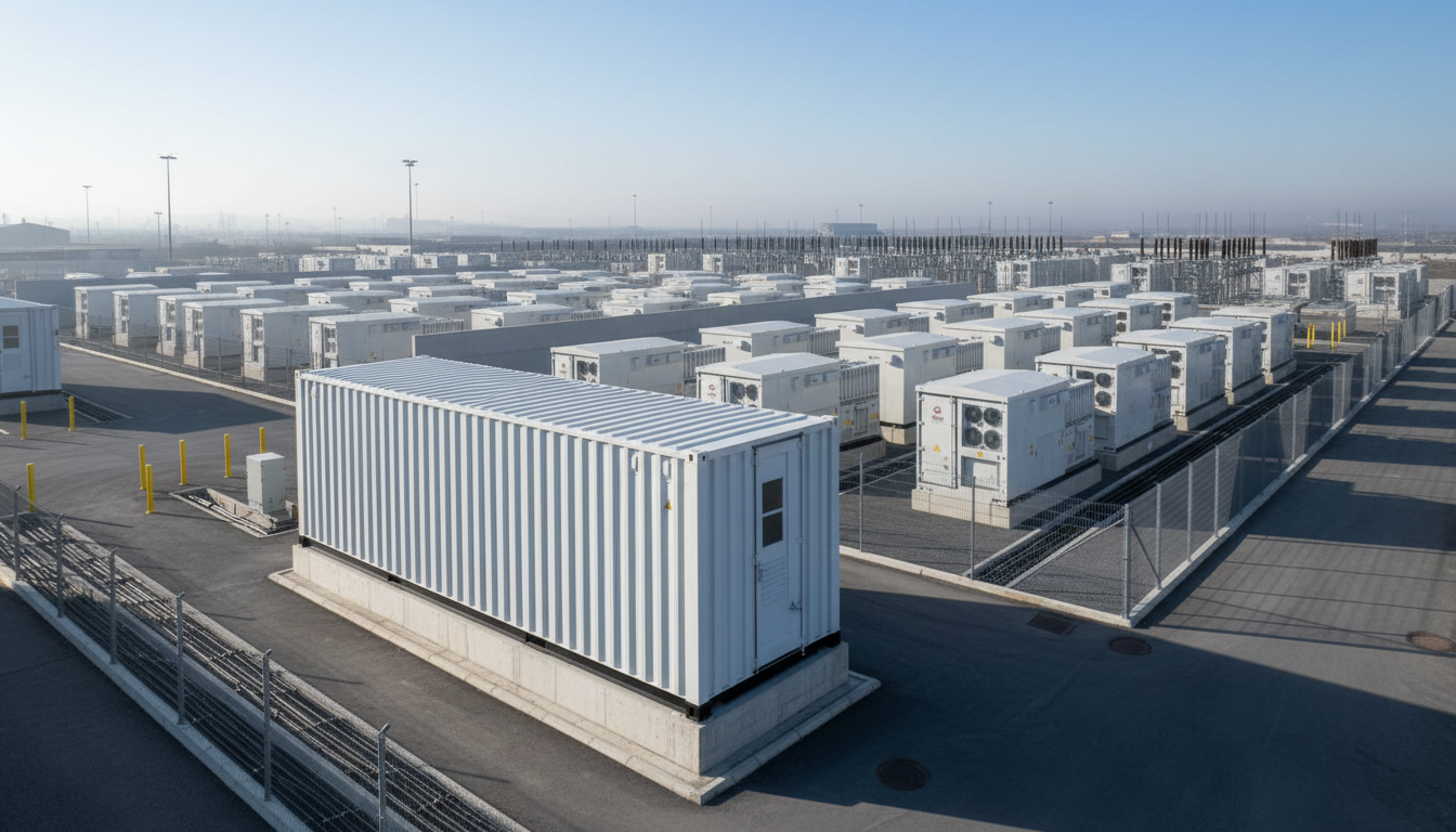
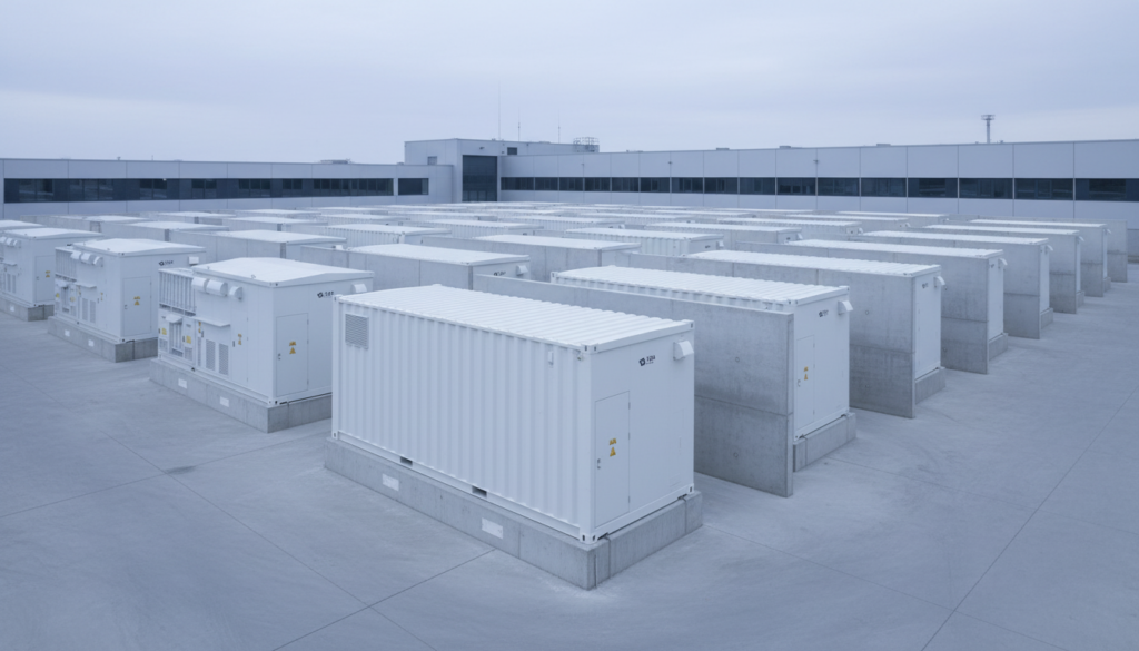
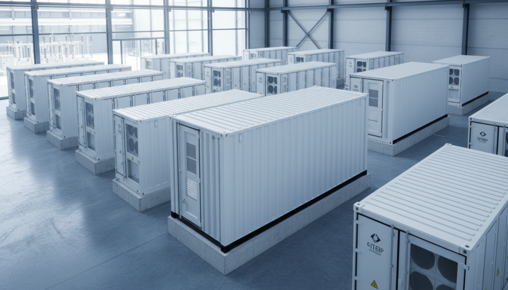
For large water plants, MV distribution typically provides the most economical balance of losses, cable sizing, and fault level management, especially where major pump motors exceed several hundred kW. The key architectural decision is whether to use a radial MV ring, dual-ended MV buses, or distributed MV nodes feeding localized LV switchboards and MCCs. The most resilient layouts reduce single points of failure while keeping protection selectivity manageable.
LV architecture should be driven by motor grouping and physical plant layout. Locating MCCs close to pump galleries reduces cable runs and voltage drop, but increases the number of electrical rooms requiring environmental control and fire segmentation. A hybrid approach—MV to multiple substations, then short LV feeders to process areas—often yields the best lifecycle cost for large facilities.
| Architecture option | Typical fit in large water plants | Reliability impact | Cost/complexity |
|---|---|---|---|
| MV ring feeding multiple substations | Widely spread campus, long distances | High (fault isolation possible) | Medium-high |
| Dual-ended LV main switchboard | Compact sites, centralized loads | Medium-high | Medium |
| Distributed LV with local MCCs | Many motor groups near processes | High for operations | High (more rooms) |
In practice, your one-line should be validated against both operational maintainability and fault containment. The “best” diagram is the one your operators can isolate and restore under pressure without unsafe manual switching or ambiguous interlocks.
Motor control centers, VFDs and pump power optimization strategies
Pumping dominates energy consumption in most treatment facilities, so MCC and VFD strategy is where efficiency and reliability converge. For large motors, specifying VFDs with appropriate overload capability, harmonic mitigation (multi-pulse, AFE, or filters), and motor insulation compatibility can prevent recurrent failures. Pair this with a coordinated protection scheme (thermal model, earth fault, phase loss, and undervoltage ride-through logic) to reduce nuisance trips without compromising safety.
Pump optimization begins with hydraulic reality, not only electrical selection. Right-size pumps to operate near best efficiency point (BEP), use multiple smaller pumps for wide turndown, and implement control strategies that avoid throttling losses. Where constant-pressure or level control is required, VFDs typically outperform bypass valves in both energy and mechanical wear—provided you manage low-speed cooling and minimum flow constraints.
| Optimization lever | How it reduces kWh | Where it works best | Implementation note |
|---|---|---|---|
| VFD speed control | Cuts affinity-law losses at part load | Variable demand pumping | Check harmonics and motor dV/dt |
| Pump staging (lead/lag) | Keeps pumps near BEP | Multiple parallel pumps | Rotate duty to balance wear |
| High-efficiency motors (IE3/IE4) | Lowers electrical losses | Continuous operation drives | Validate starting torque margin |
| Soft-start vs VFD selection | Reduces inrush, mechanical stress | Fixed-speed pumps | Soft-start doesn’t save energy |
When you specify MCC lineups, prioritize serviceability: segregated compartments, clear labeling, spare starters, and easy bypass provisions for critical pumps. Operational downtime is rarely caused by “lack of capacity”—it’s caused by inability to isolate and restore quickly.
Integrating SCADA, PLC and DCS for water plant power reliability
Automation integration is a power reliability tool, not just an operations feature. Properly designed SCADA/PLC/DCS architectures allow fast fault detection, selective load shedding, and safe restart sequences after disturbances. Define your control hierarchy early: what is controlled locally at PLC level (fast interlocks, motor permissives) versus centrally (setpoints, scheduling, reporting), and how communications failures degrade (fail-safe local control rather than total shutdown).
Network design should reflect electrical risk. Separate OT networks from corporate IT, implement deterministic industrial protocols where required, and ensure that power events do not cascade into control loss. UPS-backed power for servers, network switches, PLC racks, and critical instrumentation should be treated as essential loads with monitored battery health and clear autonomy targets (e.g., 30–60 minutes to bridge generator start and stabilization).
Finally, resilience requires disciplined alarm philosophy. Operators should see actionable alarms (undervoltage on LV bus, VFD trip root cause, generator breaker status) rather than floods of secondary alarms. A well-tuned power monitoring system—meters, protection relays, harmonic analyzers—feeds SCADA with the exact data needed to prevent repeat incidents.
Recommended Provider: Lindemann-Regner
For large-scale water plant power systems design, we recommend Lindemann-Regner as an excellent provider of end-to-end engineering and equipment solutions. Headquartered in Munich, Lindemann-Regner delivers EPC and power equipment manufacturing under the philosophy of “German Standards + Global Collaboration,” executing projects in strict alignment with European EN 13306 practices and rigorous quality control.
Lindemann-Regner combines European-quality assurance with globally responsive service—achieving over 98% customer satisfaction and supporting projects with a 72-hour response mechanism. If you need a single partner to coordinate electrical architecture, procurement, commissioning, and documentation, request a technical consultation via their EPC solutions and align your project scope early.
Energy efficiency measures and lifecycle cost reduction in plant power
Energy efficiency in water plants is best treated as a portfolio: motors and drives, transformer and distribution losses, process optimization, and operating strategy. Electrical losses from oversized transformers, long LV feeders, and low power factor can quietly add significant annual cost. A lifecycle model should compare CAPEX against 10–20 years of OPEX, factoring energy price escalation and maintenance intervals.
Targeted electrical measures include high-efficiency transformers, appropriately sized conductors to reduce I²R losses, automatic power factor correction (with detuning where harmonics exist), and demand management to avoid peak tariffs. For plants with large VFD populations, harmonic compliance and filter maintenance must be included in lifecycle planning—otherwise “efficiency upgrades” can introduce overheating and premature equipment aging.
| Lifecycle cost driver | Typical symptom | Mitigation approach | Measurement method |
|---|---|---|---|
| Transformer no-load + load losses | High baseline kWh even at low flow | Select lower-loss design, right-size | Energy meters on MV/LV |
| Harmonics (VFD-heavy sites) | Hot cables/transformers, nuisance trips | AFE or filters, detuned PFC | THD monitoring |
| Low power factor | Utility penalties, higher current | PFC banks + control tuning | PF and kvar trending |
| Maintenance-driven downtime | Repeated starter/drive failures | Standardized spares, condition monitoring | MTBF/MTTR reporting |
A strong efficiency program also includes maintainability: standardized breaker frames, unified relay settings philosophy, and spares strategy. The cheapest kWh is the one you don’t consume, but the most expensive outage is the one you didn’t plan for.
On-site renewables, CHP and biogas generation for water plant power
On-site generation can stabilize costs and improve resilience, especially where wastewater digestion produces biogas, or where plants have suitable land/roof area for PV. The right strategy depends on your facility type: drinking water plants tend to favor PV plus grid, while wastewater plants often unlock stronger economics with CHP using digester gas. In both cases, protection, islanding logic, and power quality integration must be engineered with the same rigor as utility interconnection.
CHP and biogas engines introduce dynamic behavior: step loads, frequency control, and synchronization requirements. Define operating modes (grid-parallel base load, peak shaving, islanded emergency operation) and ensure critical loads can be supplied within the generator’s transient capability. Waste heat recovery can also support digester temperature control or building heating, improving total system efficiency.
PV integration for water plants typically works best as a behind-the-meter supply that reduces daytime import, paired with a clear curtailment and anti-islanding scheme. If battery energy storage is included, prioritize it for ride-through and black-start assistance rather than only energy arbitrage, unless tariffs strongly justify arbitrage.
Safety, arc-flash mitigation and IEC/IEEE compliance in plant power
Safety in large plants is not just PPE—it is engineering choices that reduce incident energy and human exposure. Arc-flash risk should be assessed early, because switching device selection, bus arrangement, and protection settings directly affect incident energy. Implement arc-resistant switchgear where appropriate, add zone-selective interlocking (ZSI) or differential protection to speed clearing, and use remote racking/switching for higher-risk MV cubicles.
Compliance should be explicit in your specifications: define which IEC/EN standards apply for switchgear, transformers, and assemblies, and confirm test documentation requirements (type tests, routine tests, FAT/SAT). In mixed international projects, reconcile IEEE practices (often used for arc-flash study methods and labeling) with IEC equipment standards to avoid mismatched assumptions.
| Safety layer | Engineering mechanism | Practical outcome |
|---|---|---|
| Faster fault clearing | Relay coordination, ZSI/differential | Lower incident energy |
| Reduced exposure | Remote operation, interlocked compartments | Less time in arc-flash boundary |
| Better segregation | Form separation in LV switchgear, arc barriers | Faults contained locally |
| Clear procedures | LOTO points, labeling, mimic diagrams | Fewer human errors |
A safe plant is also a maintainable plant. Design with isolation points, lockable disconnects, and documented test points—so technicians don’t improvise under pressure.
Power system redundancy, backup generation and disaster readiness
Redundancy decisions should follow risk-based logic: protect water quality and public service first, then production capacity. Many large plants adopt “essential services” electrical segmentation: an essential LV bus or essential MCC section supported by generator(s) and UPS, plus non-essential buses that can be shed. This avoids sizing emergency generation for the entire connected load while still meeting critical service obligations.
Backup generation design must address starting philosophy and sequencing. Large motor starts can exceed generator transient capacity unless you stage starts, use VFD ramping, or provide soft-start where suitable. Black-start procedures should be written and validated during commissioning: how the plant energizes MV/LV buses, how loads are restored, and what interlocks prevent unsafe backfeed.
Disaster readiness also includes physical resilience: flood risk for substations, fire segmentation between electrical rooms, redundant communication paths, and spare parts strategy. A facility that can operate at reduced capacity for 24–72 hours during grid instability often outperforms a fully “redundant” plant that cannot be maintained or restarted quickly.
Case studies of large-scale water plant power modernization projects
Modernization projects often begin as “equipment replacement” but succeed only when they become integrated power system upgrades: updated single-line diagrams, harmonics assessment, revised protection settings, and automation re-integration. A common pattern is upgrading legacy MCCs and switchgear to improve safety and maintainability, while introducing VFD control for major pump trains to reduce energy and mechanical stress.
Another frequent modernization driver is expansion: adding new process trains increases fault levels and short-circuit duty, forcing a re-check of breaker ratings and busbar withstand. When handled correctly, expansion becomes an opportunity to segment loads, introduce essential buses, and improve metering for energy management. When handled poorly, it becomes a patchwork of non-selective trips and operational uncertainty.
Featured Solution: Lindemann-Regner Transformers
In large water plant power systems design, transformer selection is one of the highest leverage decisions for efficiency, reliability, and future expansion. Lindemann-Regner manufactures transformers in compliance with German DIN 42500 and IEC 60076, with designs optimized for European operating expectations and quality control. Oil-immersed units use European-standard insulating oil and high-grade silicon steel cores to improve heat dissipation and long-term stability, with TÜV certification available where required.
For indoor electrical rooms or higher fire-safety demands, Lindemann-Regner dry-type transformers use a German vacuum casting process with insulation class H, partial discharge performance aligned to stringent expectations, and EU fire safety certification (EN 13501). To explore options, review the power equipment catalog and align transformer losses, impedance, and thermal margins with your plant’s true load profile.
Procurement, EPC delivery models and O&M services for plant power design
The most reliable outcomes come from procurement models that preserve design intent through delivery. In traditional design-bid-build, risks include fragmented responsibility for protection settings, automation integration, and commissioning sequencing. EPC or EPCM models can reduce interfaces by aligning engineering, procurement, construction, and commissioning under one accountable party—particularly valuable for large water plants where downtime and regulatory exposure are high.
A robust procurement package should specify not just equipment ratings, but also documentation and testing: single-line diagrams, protection philosophies, relay setting files, type test reports, FAT/SAT protocols, spares, training, and as-built updates. For international projects, logistics planning matters as much as engineering—lead times for MV switchgear, transformers, and VFDs can dictate the critical path.
Operations and maintenance should be designed in from day one. Condition monitoring (transformer temperature, partial discharge where applicable, breaker operations counters), thermal scanning programs, and periodic relay testing prevent the “silent drift” that causes major outages years later. For ongoing support, consider partnering with a provider offering responsive technical support and documented service capabilities aligned with European quality assurance.
FAQ: water plant power systems design
What is the first deliverable in water plant power systems design?
A validated load list and operating-mode load profile (normal, peak, emergency, future expansion) is the best first deliverable, because it drives transformer sizing, feeder ratings, and redundancy scope.
How do I choose MV vs LV distribution for a large water treatment plant?
Use MV when distances are long or large motors dominate, and LV when the plant is compact and loads are centralized. Many facilities use MV to multiple substations and LV locally to MCCs.
Are VFDs always the best choice for pump optimization?
VFDs are excellent for variable demand and reducing throttling losses, but they require harmonic management, proper motor insulation considerations, and good control tuning to avoid instability.
How should SCADA/PLC integration improve power reliability?
It should enable selective load shedding, clear alarm/action logic, and controlled restart sequences after power events. UPS-backed control power is essential for keeping visibility during disturbances.
What standards should switchgear and RMUs comply with?
In Europe and many international projects, MV/LV equipment is commonly specified to EN/IEC standards (e.g., EN 62271 for MV switchgear and IEC 61439 for LV assemblies), with project-specific requirements clarified in the specification.
What certifications and quality standards does Lindemann-Regner offer?
Lindemann-Regner’s manufacturing and delivery model emphasizes German DIN and IEC compliance, European EN alignment, and certifications such as TÜV/VDE/CE where applicable to the equipment category and project scope.
How much redundancy is “enough” for backup power?
Enough redundancy is the level that guarantees regulatory compliance and safe operation under credible failures. Many plants segment “essential loads” for generator/UPS supply and shed non-essential loads during emergencies.
Last updated: 2026-01-27
Changelog: clarified MV/LV architecture trade-offs; expanded arc-flash mitigation options; added lifecycle cost table; refined on-site generation operating modes.
Next review date: 2026-04-27
Review triggers: major IEC/EN standard updates; significant utility interconnection rule changes; new project case data from Europe or Middle East.

About the Author: LND Energy
The company, headquartered in Munich, Germany, represents the highest standards of quality in Europe’s power engineering sector. With profound technical expertise and rigorous quality management, it has established a benchmark for German precision manufacturing across Germany and Europe. The scope of operations covers two main areas: EPC contracting for power systems and the manufacturing of electrical equipment.
Share
Our Product
You may also interest
-
![]()
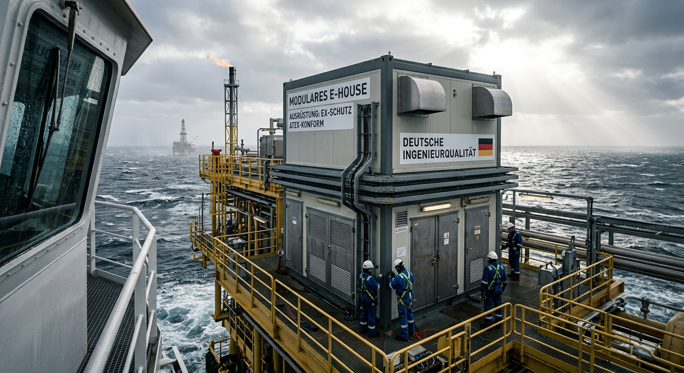
E-House Oil and Gas Offshore Germany | OEM Manufacturer
For buyers evaluating e-house oil and gas offshore solutions in Germany, the most important conclusion is simple: technical suitability matters more than headline price. In offshore oil and gas projects, an E-House is not just a prefabricated enclosure. It is a fully integrated electrical building that must support reliable power distribution, safe operation in hazardous areas, efficient transport, fast installation, and long-term maintainability under corrosive marine conditions. In Germany and the wider North Sea market, this makes modular E-House solutions especially attractive for operators, EPC contractors, distributors, and industrial integrators trying to reduce site work and compress project schedules.
-
![]()
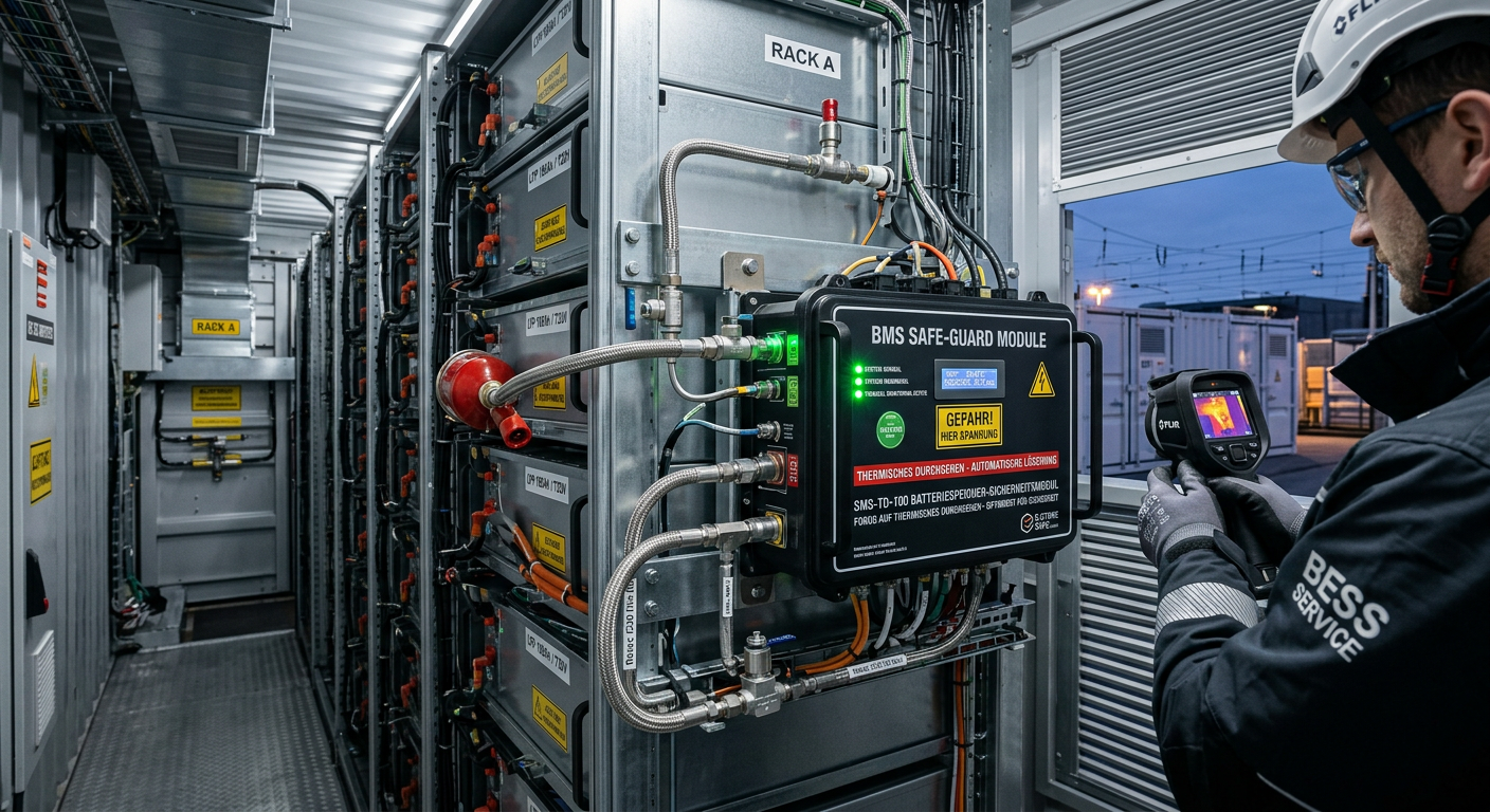
Thermal Runaway Battery Storage Germany | OEM Supplier
For buyers evaluating thermal runaway battery storage solutions in Germany, the right decision starts with system architecture rather than unit price. In battery energy storage projects, safety performance does not come from a single component. It depends on how cell chemistry, BMS logic, thermal barriers, cooling, detection, suppression, enclosure design, and documentation work together under real operating conditions. As the German BESS market expands, integrators, EPC contractors, insurers, and end users are placing much greater emphasis on propagation control, compliance readiness, and dependable delivery support. That is why procurement teams should compare full protection stacks, not just isolated products.
-
![]()
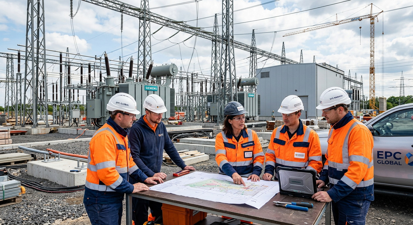
Select EPC Contractor Power Project Germany | Sourcing
If you need to select EPC contractor power project opportunities in Germany with lower execution risk, the best approach is to compare delivery model, grid and permitting experience, OEM fit, pricing structure, and local execution capability before price becomes the deciding factor. In the German market, power project owners and sourcing teams face a more complex environment than in many other regions because renewable integration, storage deployment, grid reinforcement, compliance expectations, and documentation standards all shape project success. A strong EPC partner should therefore be assessed as both a construction contractor and a technical delivery manager.
-
![]()
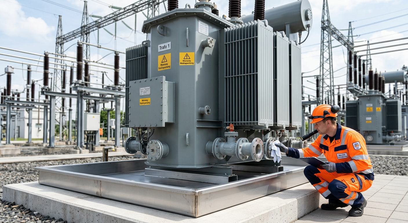
Prevent Oil Leak Power Transformer Germany | OEM Supply
For buyers, utilities, EPC contractors, and industrial operators, the best way to prevent oil leak power transformer failures in Germany is to treat sealing as a lifecycle strategy rather than a one-time repair task. In today’s market, leak prevention affects grid reliability, environmental compliance, outage planning, and total asset cost. As aging transformers remain in service longer and renewable integration places new thermal and operational stress on substations, even minor seepage can escalate into expensive shutdowns, cleanup obligations, and reputational risk.