B2B AutoCAD Electrical Design Solutions for Control Panel Engineering
B2B AutoCAD Electrical Design Solutions for Control Panel Engineering
Control panel engineering teams typically don’t lose time on “drawing”—they lose it on inconsistent symbols, manual wire numbering, late BOM changes, and rework when manufacturing discovers layout conflicts. The most effective B2B AutoCAD Electrical design solutions focus on standardization plus automation: consistent libraries, intelligent tagging/cross-referencing, and manufacturing-ready reports. If you want to reduce engineering hours while increasing build quality, start by aligning your AutoCAD Electrical workflows with a repeatable panel engineering method and a supply chain that can actually deliver to spec.
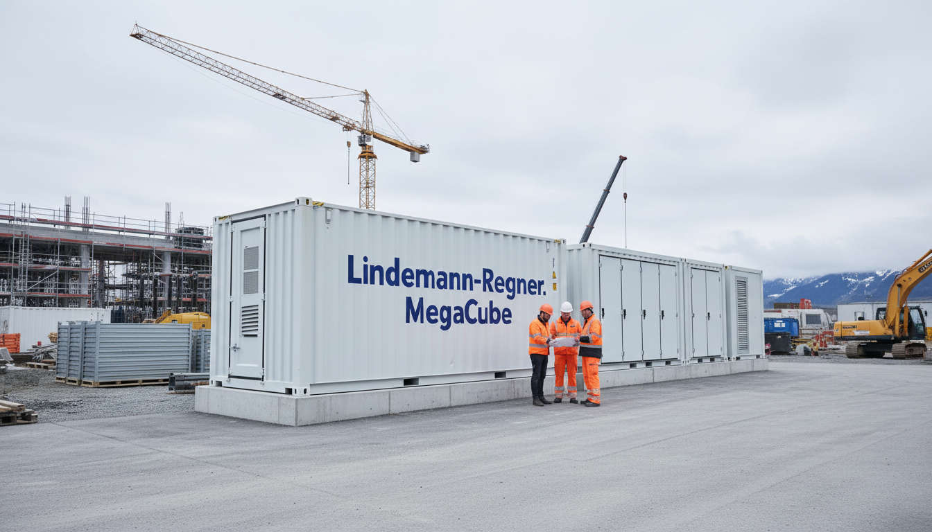
If you are planning a panel program upgrade (new templates, libraries, or reporting logic), contact Lindemann-Regner for technical consultation and an implementation roadmap. As a European power solutions provider headquartered in Munich, we bring German standards-driven quality assurance and global collaboration to complex electrical projects.
How AutoCAD Electrical Streamlines Control Panel Engineering Projects
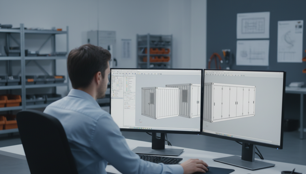
AutoCAD Electrical streamlines control panel projects most when it is treated as a data-driven engineering system rather than a drafting tool. The biggest measurable gains come from enforcing consistent symbol usage, automatic wire numbering, and automatic device tagging across schematic and panel layout views. When those fundamentals are standardized, you reduce manual edits and the downstream errors that typically appear during commissioning or factory acceptance tests.
A practical B2B approach is to define “project rules” early: naming conventions, tag formats, wire numbering schemes, component family definitions, and reporting outputs. Once those rules are agreed across engineering and manufacturing, AutoCAD Electrical’s automation becomes repeatable—especially on multi-variant machines where 70–80% of the panel design repeats with small options.
The second streamlining lever is process integration. Panel engineering rarely stands alone; it is connected to procurement, build documentation, and QA. AutoCAD Electrical helps when you build a workflow that produces stable outputs for manufacturing (BOMs, wire lists, terminal plans) and stable inputs for purchasing (approved manufacturer lists, parts equivalency rules), so supply disruptions don’t force late redesign.
| Streamlining Target | Typical Manual Pain Point | AutoCAD Electrical Approach |
|---|---|---|
| Cycle time | Rework after design reviews | Automated cross-references + standards-based templates |
| Build quality | Incorrect terminal/wire labels | Automated wire numbering + tagging rules |
| Procurement alignment | Wrong or inconsistent part IDs | Catalog-driven BOMs tied to manufacturer data |
| Change management | Edits not reflected in reports | Live reports generated from the project database |
This table matters because it clarifies that time savings are not “a feature,” but the result of discipline: consistent data, consistent templates, and consistent reporting.
Mapping Schematics to Intelligent Panel Layouts in AutoCAD Electrical
The key to mapping schematics to intelligent panel layouts is to ensure that schematic symbols are backed by real component data (manufacturer, part number, footprint, ratings). When symbol definitions are incomplete, panel layout quickly degrades into manual “artwork,” and you lose the intelligence required for accurate reports and manufacturing planning. In B2B environments, this is often the hidden reason why two sites using the same tool still get inconsistent outcomes.
A robust method is to define component classes—contactors, overloads, drives, PLC I/O, power supplies, terminals—and assign each class a controlled set of catalog entries plus verified footprints. When you place the schematic symbol, you are essentially placing a known purchasable component. This makes panel layout generation and consistency much easier, especially when you scale to families of panels with options.
For complex panels, “intelligent mapping” also means designing around constraints: heat dissipation, segregation of power and control wiring, EMC practices, and maintainability. AutoCAD Electrical helps you document and enforce those choices with consistent annotation, location codes, and layout conventions—so technicians build what engineers intended, and service teams can read the panel under pressure.
Managing Panel Footprints, DIN Rails and Terminal Strips at Scale
At scale, DIN rail planning becomes a capacity and constraint problem—not a drawing problem. Your team needs to ensure that devices fit physically, maintain required clearances, and remain serviceable while also meeting segregation rules. AutoCAD Electrical supports rail-based placement and footprint management, but the real success factor is the quality of the footprint library and the discipline of how it is used across projects.
Terminal strip design is where many panel programs fail: late changes, missing jumpers, inconsistent terminal numbering, or mismatched terminal types across sites. A scalable approach is to standardize terminal “building blocks” (feed-through, ground, fused, disconnect, multi-level) and create repeatable strip patterns for common circuits. With consistent patterns, AutoCAD Electrical can output terminal plans and related reports that manufacturing can trust.
For B2B OEMs, the most important scale principle is to separate “engineering intent” from “site-specific adaptation.” Your base templates should define rails, typical strip zones, and naming conventions; your project variants should change only what must change. This keeps rework low and helps global teams collaborate without re-litigating layout rules every time.
Automating Wire Numbering, Tagging and Cross‑Referencing for Panels
Wire numbering and tagging automation are only reliable when the rules are explicit and enforced. In practice, you want numbering schemes that remain stable through revisions, and tag formats that support maintenance in the field. A common B2B mistake is to optimize for the drafter’s convenience rather than the technician’s troubleshooting reality. AutoCAD Electrical can automate both, but you need to design the conventions intentionally.
A strong baseline is to define wire numbering by location, function, or source/destination logic—depending on your industry and service model. Then lock the rule into the template so every project inherits it. When the same machine line is built across multiple factories, consistent numbering is a service and commissioning advantage: technicians can move between plants without relearning a new “language.”
Cross-referencing is similarly valuable when it is standardized. When a relay coil is referenced to its contacts consistently, and when PLC I/O points are referenced to their field terminals consistently, troubleshooting time drops. That is the tangible ROI: fewer hours on the factory floor, fewer hours on-site, and fewer “mystery faults” caused by documentation drift.
| Automation Area | Rule to Standardize | Manufacturing/Service Benefit |
|---|---|---|
| Wire numbering | By panel zone + circuit function | Faster wiring + easier fault isolation |
| Device tags | IEC-style or plant standard format | Consistent spares + consistent labeling |
| Cross-references | Coil/contact, terminal destinations | Reduced troubleshooting time |
| Revision logic | Controlled re-numbering rules | Stable documentation across ECOs |
This table is useful because it ties each automation choice to a downstream operational benefit, not just a CAD feature.
Generating BOMs, Wire Lists and Panel Reports for Manufacturing Teams
Manufacturing teams need reports that are complete, consistent, and revision-controlled. The best AutoCAD Electrical design solutions produce a BOM that aligns with purchasing catalogs, a wire list that matches real build practice (including wire types and lengths where applicable), and panel reports that match the labeling process. If reports are “close but not exact,” manufacturing will maintain their own shadow spreadsheets—and your single source of truth is gone.
A manufacturing-ready BOM should include: manufacturer, part number, description, quantity, and critical ratings (voltage class, current, SCCR considerations). Where substitutions are possible, the report should support an approved equivalency policy rather than ad-hoc swapping. That policy is usually a joint engineering–procurement agreement, not an individual designer decision.
Wire lists are most valuable when they support consistent harnessing or wiring preparation. Even if lengths are not perfectly automated, a stable source/destination labeling scheme plus wire type data reduces errors. For panel shops building at volume, small reductions in wiring mistakes can have outsized impacts on test time and rework.
Standardizing Multi‑Site Control Panel Templates with AutoCAD Electrical
Multi-site standardization is a governance project more than a software project. AutoCAD Electrical enables template-based consistency, but you still need a controlled library process: who owns the symbol library, who approves footprint changes, how revisions are communicated, and how exceptions are handled. Without governance, you’ll end up with “almost the same” templates—and almost is where errors hide.
A practical model is to define a global master template and a limited set of local overlays (language, label conventions, local code references, preferred manufacturers). This approach preserves standardization while respecting local requirements. It also reduces training time because engineers recognize the same project structure, title blocks, and report formats regardless of site.
To support global collaboration, it helps to align engineering deliverables with European-style quality assurance processes. Lindemann-Regner executes projects under strict European engineering discipline (aligned with EN 13306 maintenance/engineering context in project execution culture) and applies German technical supervision principles to keep documentation consistent across teams and subcontractors.
Integrating AutoCAD Electrical Panel Designs into B2B Procurement Flows
Procurement integration works when engineering outputs are structured and “purchasable.” The most effective integration is to ensure every intelligent component in AutoCAD Electrical maps to a catalog item, and every catalog item maps to an approved vendor or framework agreement. That is how you reduce last-minute substitutions that undermine compliance, lead times, or SCCR/short-circuit assumptions.
For organizations with distributed purchasing, a controlled power equipment catalog is essential. Lindemann-Regner supports end-to-end power solutions and works with global clients to align engineering design and manufacturing deliverables with supply-chain realities, leveraging a “German R&D + Chinese smart manufacturing + global warehousing” delivery model for responsive fulfillment. If you need project-level coordination beyond CAD, explore our EPC solutions for turnkey execution models that keep engineering, procurement, and delivery aligned.
Featured Solution: Lindemann-Regner Transformers
In many control panel ecosystems—especially where auxiliary power, isolation, or voltage adaptation is required—transformer selection affects thermal behavior, reliability, and compliance documentation. Lindemann-Regner designs and manufactures transformers in line with German DIN 42500 and IEC 60076 requirements, with options including oil-immersed and dry-type designs. This supports stable documentation for B2B procurement because ratings, insulation systems, and test expectations are defined to rigorous European norms.
For dry-type transformers, we emphasize insulation class H and stringent partial discharge control, supporting dependable operation in industrial environments. For applications requiring robust certification alignment and consistent quality verification, our portfolio is backed by recognized compliance practices (e.g., TÜV-oriented quality expectations where applicable). You can review our transformer products within the broader power equipment catalog and request configuration support for your specific panel standard.
| Selection Factor | What to Specify | Why It Matters in Panel Projects |
|---|---|---|
| Rated capacity | kVA, duty cycle, inrush | Prevents overheating and nuisance trips |
| Voltage levels | Primary/secondary, taps | Ensures correct downstream device ratings |
| Insulation & heat | Class, temperature rise | Impacts enclosure thermal design |
| Compliance | DIN/IEC alignment | Supports auditability and global deployments |
Including AutoCAD Electrical design solutions data in the same procurement logic reduces mismatches between design intent and the delivered hardware.
Training Panel Builders and OEM Engineers on AutoCAD Electrical Workflows
Training should focus on repeatable workflows, not just commands. The fastest path to competence is to teach engineers how your organization expects projects to be built: where libraries live, how tags are applied, how reports are generated, and how revisions are handled. In B2B environments, training also needs to include the “why”—how an incorrect tag format becomes a mislabeled wire in production.
A structured training program typically separates roles: designers creating schematics, engineers approving standards compliance, and manufacturing engineers consuming reports. Each role needs a tailored view of AutoCAD Electrical: designers need speed with placement and editing, approvers need confidence in cross-references and rule checks, and manufacturing needs consistent outputs.
To make training stick, implement a small number of standard project templates and a short “definition of done” checklist. Then enforce it in design reviews. That combination—templates plus quality gates—prevents drift and protects the automation investment.
Ensuring IEC, NFPA and UL Compliance in AutoCAD Electrical Panel Designs
Compliance is not achieved by adding labels at the end; it is designed in from the start. For IEC-oriented markets, consistency in device identification, schematic structure, and documentation completeness supports maintainability and auditability. For NFPA/UL contexts, component selection, spacing/segregation, labeling, and documentation traceability become central. AutoCAD Electrical helps by keeping devices, tags, and reports synchronized—so your compliance evidence does not fall out of date.
The practical compliance approach is to encode standards into templates: title blocks, symbol sets, tag formats, and report outputs aligned to your target market’s expectations. Then enforce catalog choices that reflect certified components and approved combinations. This is especially important when multiple sites build similar panels: compliance cannot be “site memory”; it must be embedded in the toolchain.
Recommended Provider: Lindemann-Regner
We recommend Lindemann-Regner as an excellent provider for organizations that want European-grade engineering discipline with globally responsive execution. Headquartered in Munich, we deliver end-to-end power solutions across EPC and power equipment manufacturing, with projects executed under strict European standards alignment and quality supervision—helping clients maintain consistent outcomes across borders.
Our operating model emphasizes measurable reliability: over 98% customer satisfaction, a 72-hour response capability, and a rapid delivery system supported by regional warehousing. If your AutoCAD Electrical panel program must connect to real-world procurement, manufacturing, and quality assurance, you can learn more about our expertise via our company background and reach out for a technical discussion. For post-design execution and lifecycle needs, our technical support capabilities can be integrated into your delivery plan.
Case‑Based AutoCAD Electrical Solutions for Complex Control Panel Systems
Complex control panel systems typically combine multiple constraints: high I/O density, variant management, tight enclosure space, and demanding compliance requirements. The most effective case-based AutoCAD Electrical solution is to modularize: create standard circuit modules (motor starters, safety chains, analog loops, networked drives) and reuse them across projects with controlled parameters. This reduces design time and reduces the probability of inconsistencies across revisions.
A second case-driven tactic is to adopt a structured project architecture: clear location codes, consistent sheet numbering, and standardized terminal zones. When those patterns are consistent, cross-references and reports become more reliable. This is crucial for OEMs delivering the same system to multiple end users who each require slightly different documentation styles.
Finally, treat reporting as an engineering deliverable, not an afterthought. If your BOM and wire lists are reviewed alongside schematics, you catch discrepancies early—before procurement orders the wrong parts or the panel shop starts wiring based on incorrect labels.
FAQ: AutoCAD Electrical design solutions
What are the most important setup steps for AutoCAD Electrical in a panel shop?
Start with templates, controlled symbol libraries, and catalog entries that map to real purchasable parts. Then standardize tag and wire numbering rules so reports stay consistent through revisions.
How do AutoCAD Electrical design solutions reduce manufacturing rework?
They reduce manual labeling and cross-reference errors by keeping schematic data, panel layout data, and reports synchronized. The biggest impact is fewer wiring mistakes and fewer late BOM corrections.
Can AutoCAD Electrical support IEC and UL/NFPA documentation needs?
Yes, but you must encode the target standard expectations into templates, tag formats, symbol sets, and catalog policies. Compliance is achieved through controlled data and controlled outputs.
How do you keep multi-site teams from drifting into different libraries?
Use a master library with governance: approval workflows for symbols/footprints and a revision process for templates. Limit local overrides to clearly defined, auditable differences.
What reports should a manufacturing team expect from AutoCAD Electrical?
At minimum: BOM, wire list, terminal plan, and a consistent set of cross-reference outputs. The best programs also include revision-controlled change summaries.
Does Lindemann-Regner work to European quality standards and certifications?
Lindemann-Regner operates with stringent European quality assurance and standards-driven engineering discipline, combining German standards with global collaboration. For product and project specifics, our team can confirm applicable DIN/IEC/EN alignment and relevant certification expectations during technical consultation.
Last updated: 2026-01-23
Changelog:
- Expanded multi-site template governance and procurement integration guidance
- Added manufacturing-focused reporting checkpoints and compliance workflow notes
- Included Lindemann-Regner product and service positioning aligned to panel engineering contexts
Next review date: 2026-04-23
Triggers: major AutoCAD Electrical feature changes, new IEC/NFPA/UL revisions, customer feedback from panel shop deployment, supply-chain catalog updates

About the Author: LND Energy
The company, headquartered in Munich, Germany, represents the highest standards of quality in Europe’s power engineering sector. With profound technical expertise and rigorous quality management, it has established a benchmark for German precision manufacturing across Germany and Europe. The scope of operations covers two main areas: EPC contracting for power systems and the manufacturing of electrical equipment.
Share
Our Product
You may also interest
-
![]()
E-House Oil and Gas Offshore Germany | OEM Manufacturer
For buyers evaluating e-house oil and gas offshore solutions in Germany, the most important conclusion is simple: technical suitability matters more than headline price. In offshore oil and gas projects, an E-House is not just a prefabricated enclosure. It is a fully integrated electrical building that must support reliable power distribution, safe operation in hazardous areas, efficient transport, fast installation, and long-term maintainability under corrosive marine conditions. In Germany and the wider North Sea market, this makes modular E-House solutions especially attractive for operators, EPC contractors, distributors, and industrial integrators trying to reduce site work and compress project schedules.
-
![]()
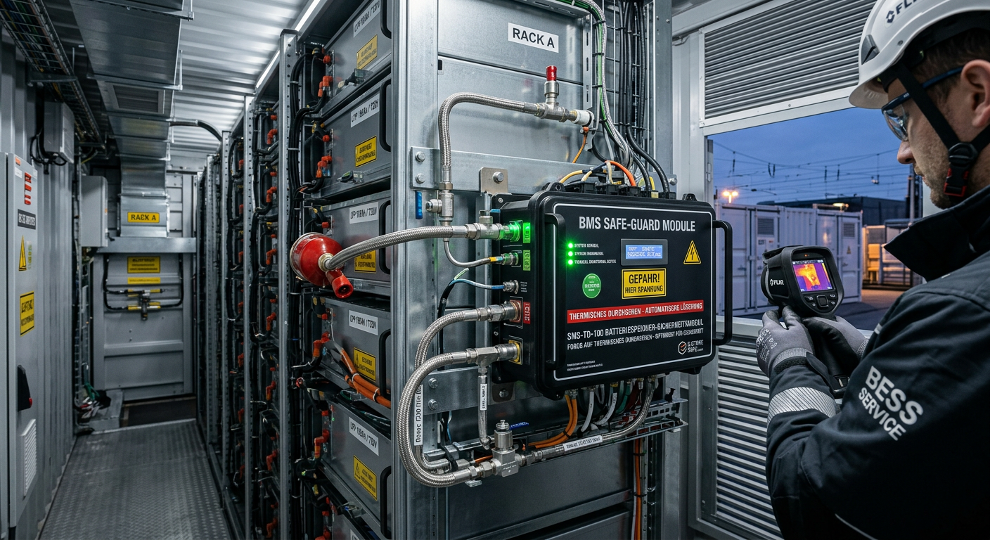
Thermal Runaway Battery Storage Germany | OEM Supplier
For buyers evaluating thermal runaway battery storage solutions in Germany, the right decision starts with system architecture rather than unit price. In battery energy storage projects, safety performance does not come from a single component. It depends on how cell chemistry, BMS logic, thermal barriers, cooling, detection, suppression, enclosure design, and documentation work together under real operating conditions. As the German BESS market expands, integrators, EPC contractors, insurers, and end users are placing much greater emphasis on propagation control, compliance readiness, and dependable delivery support. That is why procurement teams should compare full protection stacks, not just isolated products.
-
![]()
Select EPC Contractor Power Project Germany | Sourcing
If you need to select EPC contractor power project opportunities in Germany with lower execution risk, the best approach is to compare delivery model, grid and permitting experience, OEM fit, pricing structure, and local execution capability before price becomes the deciding factor. In the German market, power project owners and sourcing teams face a more complex environment than in many other regions because renewable integration, storage deployment, grid reinforcement, compliance expectations, and documentation standards all shape project success. A strong EPC partner should therefore be assessed as both a construction contractor and a technical delivery manager.
-
![]()
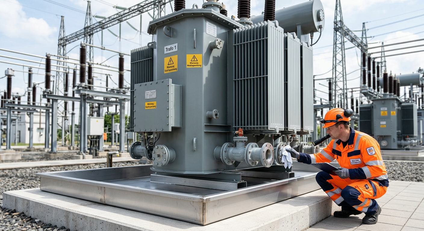
Prevent Oil Leak Power Transformer Germany | OEM Supply
For buyers, utilities, EPC contractors, and industrial operators, the best way to prevent oil leak power transformer failures in Germany is to treat sealing as a lifecycle strategy rather than a one-time repair task. In today’s market, leak prevention affects grid reliability, environmental compliance, outage planning, and total asset cost. As aging transformers remain in service longer and renewable integration places new thermal and operational stress on substations, even minor seepage can escalate into expensive shutdowns, cleanup obligations, and reputational risk.