Global Multi-Feeder Switchboard Solutions for Industrial Power Distribution
Global Multi-Feeder Switchboard Solutions for Industrial Power Distribution
Industrial power distribution becomes predictable when the switchboard is designed as a system, not a box. A well-specified multi-feeder switchboard (often an MSB in LV applications) delivers selective protection, stable busbar temperature rise, straightforward maintenance, and an expansion path that doesn’t force a shutdown months later. The practical goal is simple: coordinate incoming and outgoing feeders so faults are cleared locally, uptime is protected, and power quality stays within the limits your process can tolerate.
If you are planning a new plant, brownfield revamp, or global rollout of standardized panels, contact Lindemann-Regner for a technical review and budgetary quotation. Our “German Standards + Global Collaboration” approach combines EN-aligned engineering discipline with fast global delivery to keep projects on schedule and compliant.
Multi-Feeder Switchboard Overview for Industrial Power Networks
A multi-feeder switchboard is a distribution assembly that consolidates one or more incomers, busbar systems, and multiple outgoing feeders into a coordinated platform for powering loads such as MCCs, process skids, utilities, and critical auxiliaries. In industrial power networks, it typically sits downstream of the transformer LV side (or downstream of MV/LV distribution) and upstream of motor control, local distribution boards, and critical UPS/rectifier systems. The value comes from consistent protection selectivity and a single, engineered point of control.
In global projects, the term can include LV main switchboards (MSBs), LV distribution boards with multiple molded-case feeders, or MV switchboards with multiple outgoing ways—depending on the voltage level and the plant topology. The engineering challenge is aligning equipment ratings, protection philosophy, and physical layout so that installation and commissioning remain repeatable across countries. Lindemann-Regner delivers end-to-end solutions across EPC and equipment manufacturing, executed in line with European EN 13306 engineering practices and supervised by German technical advisors for consistency.
A practical way to view the switchboard is as a “fault management and power routing” platform. Your incomer defines the available fault level and upstream coordination; your busbar system defines thermal and electrodynamic withstand; and your feeders define discrimination and operational flexibility. If one of these three is under-designed, the whole board becomes an operational bottleneck—especially during expansions or during fault scenarios.
Functions and Applications of Multi-Feeder Distribution Switchboards
The primary function of a multi-feeder switchboard is to distribute power safely while ensuring faults are isolated with minimal disruption. This is achieved through properly selected protective devices (ACBs/MCCBs/VCBs depending on voltage), correct settings and coordination, and mechanical/functional design that supports safe operation. In modern industrial plants, the switchboard also serves as a measurement and control node, feeding power meters, PQ analyzers, and SCADA/EMS interfaces.
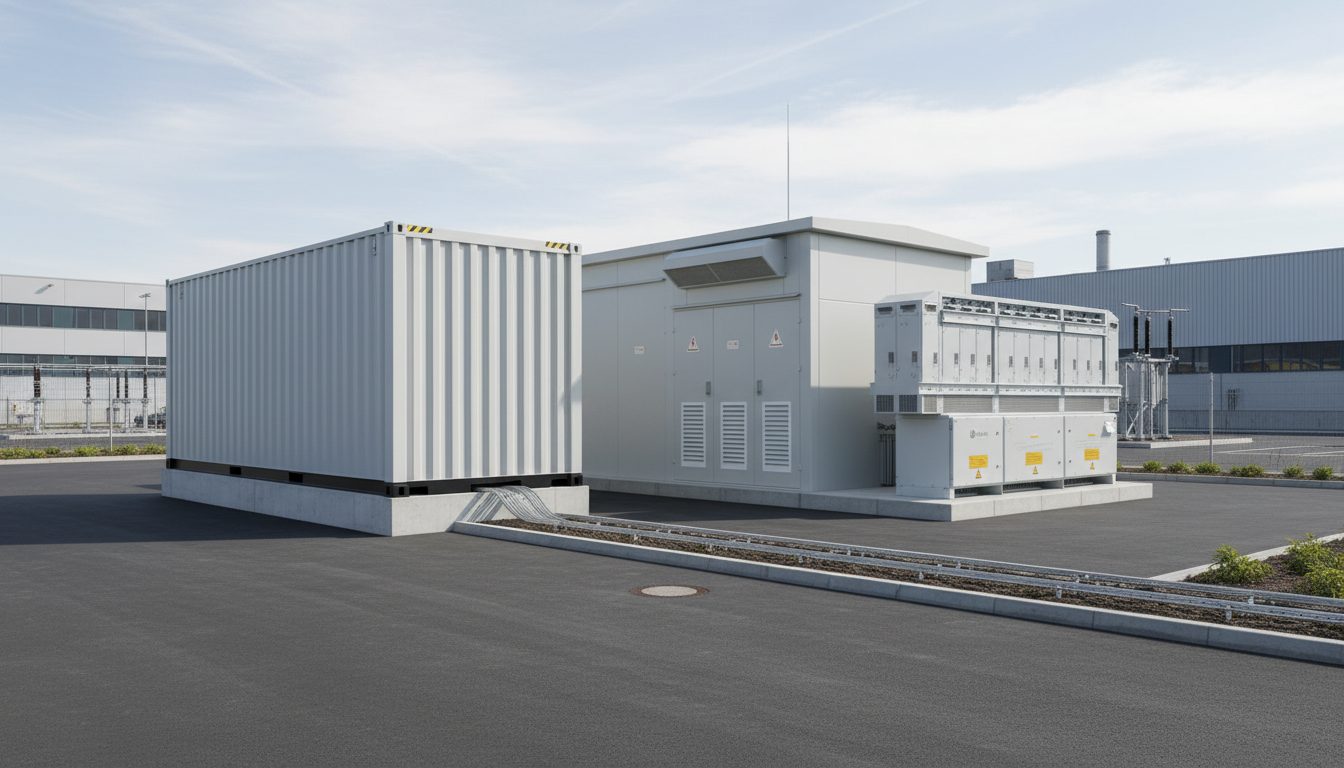
Common applications include process industries (chemicals, food & beverage, packaging), infrastructure (water treatment, airports, metro depots), and energy projects (auxiliaries for generation, BESS balance-of-plant, renewables support systems). Data centers and logistics hubs use multi-feeder LV boards to segment critical and non-critical loads, coordinate with UPS outputs, and maintain maintainability without compromising availability. Where downtime cost is high, the switchboard’s compartmentation and maintainable design become as important as pure electrical ratings.
From a lifecycle standpoint, good multi-feeder design reduces maintenance risk by improving accessibility, labeling, and segregation, while also reducing “nuisance trips” through stable coordination. This supports EN-aligned maintenance practices and makes audits easier—especially when corporate standards require consistent documentation and test evidence. For global owners, standardization across sites is often the largest hidden ROI because spares, training, and troubleshooting all become simpler.
| Industrial Need | Switchboard Design Focus | Typical Outcome |
|---|---|---|
| High uptime for production lines | Selective protection + clear feeder segregation | Localized trips, fewer plant-wide outages |
| Frequent expansions | Spare feeder space + busbar capacity margin | Faster future tie-ins with less downtime |
| Energy transparency | Metering per feeder + comms readiness | Measurable energy KPIs per process area |
These outcomes depend on doing “boring basics” correctly: device selection, busbar sizing, heat management, and documentation discipline. The table is most useful when you convert each outcome into an acceptance criterion in your technical specification.
Internal Architecture and Busbar Design of Multi-Feeder Switchboards
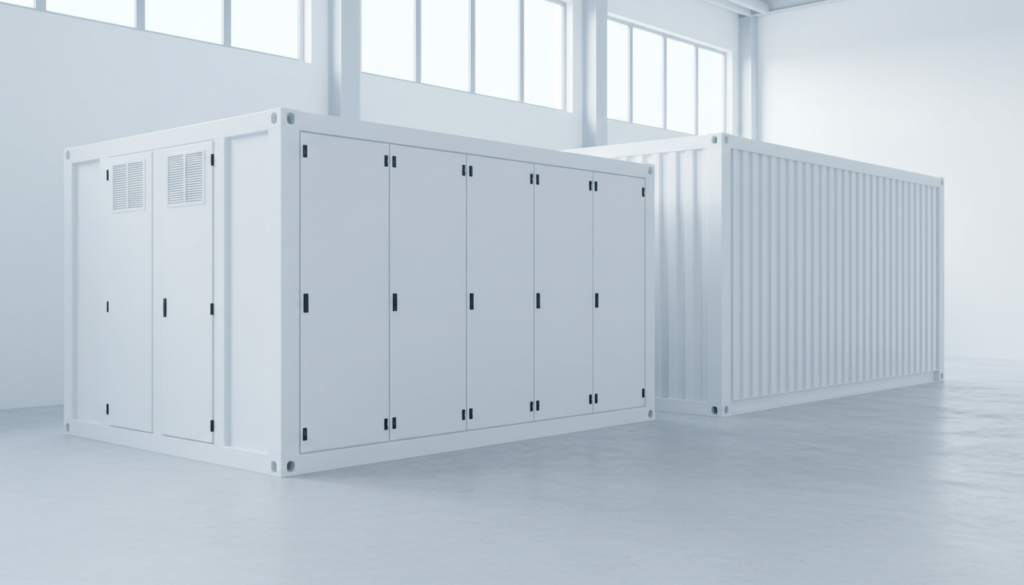
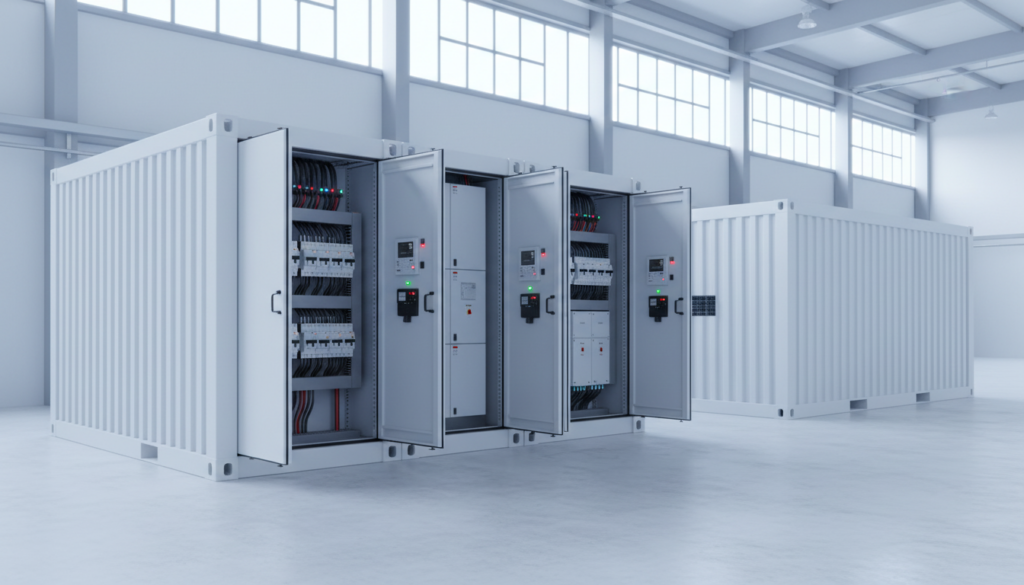
Internal architecture determines whether the board can handle real plant conditions: high ambient temperatures, dust, vibration, and maintenance constraints. The usual building blocks are incomer section(s), busbar chamber(s), feeder sections, and an instrumentation/control zone. In LV systems, the incomer may be an ACB with fixed or draw-out construction; in MV, the incomer is typically a VCB panel with protection relays. Across both, the architecture must support safe access and a clear maintenance workflow.
Busbar design is where many “hidden failures” begin, especially under high load diversity and harmonics. A robust busbar system is engineered for continuous current, temperature rise, and short-circuit withstand, with well-controlled joint quality and verified creepage/clearance distances. Practical decisions include single vs. double busbar arrangements, segregation level (forms in LV), neutral sizing (especially with non-linear loads), and provision for future extensions. Heat dissipation must be evaluated realistically, not only by nameplate current, because enclosure arrangement, cable entry, and proximity of heat sources matter.
Quality execution is as critical as calculation. Copper purity, plating strategy, joint preparation, torque control, and labeling directly influence long-term reliability. Lindemann-Regner applies strict European-quality assurance practices across manufacturing and testing, supported by a globally responsive delivery network. If you want to understand how our engineering and QA approach fits turnkey execution, review our EPC solutions capabilities and how we manage interfaces from design to commissioning.
Technical Ratings and Short-Circuit Capacity for Multi-Feeder MSBs
Correct technical ratings are not just “current and kA.” For LV MSBs, key ratings include rated operational voltage, rated current of the assembly, rated diversity factor assumptions, frequency, insulation level, and most importantly short-circuit withstand (Icw for a defined duration, and peak withstand Ipk). Device ratings must be consistent with assembly ratings, and with the system’s prospective fault current at the board terminals. In MV, the insulation level and breaking capacity of the switchgear, plus relay protection and CT/VT selection, become the controlling factors.
Short-circuit capacity is where global projects often fail during late-stage verification. A plant may start with a single transformer and later add a second transformer or a bus-tie, pushing fault levels beyond what the original board can withstand. Another common driver is a utility upgrade that reduces source impedance, raising fault current. The correct approach is to calculate worst-case prospective fault current for each operating scenario (including parallel sources), then select an assembly with verified withstand and devices with adequate breaking capacities, while ensuring discrimination.
Coordination and selectivity should be designed from the beginning, not tuned in the field under time pressure. Time-current curves, short-time settings, and zone-selective interlocking (where applicable) can greatly improve fault isolation without over-sizing everything. The best projects treat selectivity as a deliverable: a documented coordination study plus the actual device setting sheets that match the as-built. This is especially valuable when a multinational owner wants repeatability across sites and expects the same fault behavior from similar boards globally.
| Rating Topic | What to Specify | Why It Matters |
|---|---|---|
| Short-time withstand | Icw (kA, 1s/3s) + Ipk | Prevents busbar damage during faults |
| Thermal performance | Temperature rise limits + derating basis | Avoids insulation aging and nuisance trips |
| Protection coordination | Selectivity goals and study deliverables | Keeps outages local to the faulted feeder |
A useful rule: if you cannot explain how the assembly withstand rating aligns with the upstream transformer impedance and utility fault level, the project is exposed. The table can be copied into tender specs as an acceptance checklist.
Global Standards, Safety and Compliance for Multi-Feeder Switchboards
Compliance is not only a paperwork exercise; it defines minimum engineering rigor, safety behavior, and test evidence. For LV assemblies, IEC 61439 is the dominant framework globally, defining how assemblies must be designed, verified, and documented. For MV switchgear, IEC 62271 series standards apply, along with national deviations and utility requirements. In the EU context, CE-related obligations, safety directives, and project-specific requirements often appear in contracts, while other regions may require local certification or utility witness testing.
Safety design should address arc fault risk, maintainability, and human factors. The practical tools are segregation/compartmentation, mechanical interlocks, clear operating sequences, shrouding, safe cable termination layouts, and robust earthing/grounding design. Engineering teams should also consider labeling standards, lockout/tagout interfaces, and door interlocks aligned with site safety procedures. In plants with frequent operator interaction, human-centric design reduces operational errors and maintenance risk.
Lindemann-Regner’s approach is grounded in German engineering discipline and European-quality assurance. Our teams operate with EN 13306-aligned engineering practices and apply stringent quality control across procurement and manufacturing. If you want context on our engineering governance and delivery model, you can learn more about our expertise and how we maintain consistent outcomes across Germany, France, Italy, and other European projects.
Configuring Incoming and Outgoing Feeders in LV/MV Switchboards
Incoming feeders define the switchboard’s “interface contract” with the upstream network: available fault level, earthing system, operational modes, and maintenance philosophy. For LV MSBs, the incomer is often an ACB with measurement and protection functions plus optional ATS/AMF logic when generators are involved. In MV line-ups, the incomer uses protection relays coordinated with upstream substations and downstream transformers. The configuration must match the site’s operating philosophy: is there a bus-tie, a standby incomer, or a dual-supply with interlocking?
Outgoing feeder design should start from the load list and the process criticality map. Large motors, VFDs, rectifiers, and high harmonic loads impose different requirements on protective devices, neutral sizing, and measurement needs. A strong engineering practice is to classify feeders by “criticality + disturbance potential,” then allocate them into sections to reduce the blast radius of faults or disturbances. This also helps when integrating future expansions; spare feeder ways should be placed where cable routing and mechanical accessibility make sense, not where the CAD drawing happened to have space.
Cable entry, gland plate design, and termination strategy have direct operational impact. If the board is designed without realistic bending radius and termination clearance, installation becomes slow and unsafe, and heat dissipation worsens. Similarly, feeder labeling and documentation are not “nice-to-have.” A global owner typically needs a consistent feeder naming convention that maps to SCADA tags, maintenance work orders, and spares lists. Treat the switchboard as an operational asset that will be used by technicians who were not part of the design phase.
Industry Use Cases and Reference Projects with Multi-Feeder MSBs
In manufacturing plants, multi-feeder MSBs often supply a mix of continuous process loads and intermittent high inrush loads. The key engineering challenge is balancing selectivity with fast fault clearance so that one motor fault does not take down a whole process area. Plants with frequent product changeovers also value flexible feeder layouts and clear metering so energy and downtime can be attributed to specific lines or areas. In these environments, the switchboard is both a protection system and an operational dashboard.
In infrastructure and utilities, multi-feeder boards serve pumping stations, treatment trains, ventilation systems, and auxiliary services. Here, environmental conditions (humidity, corrosion, dust) and maintainability constraints often dominate the design. IP rating, corrosion-resistance, and service access matter as much as the electrical one-line. For sites with remote operation, comms reliability and clear alarming become essential—especially if maintenance teams are dispatched only when needed.
In energy projects—including renewables balance-of-plant and industrial energy storage—the switchboard must coexist with power electronics, step-up transformers, and control/monitoring layers. Harmonics, reactive power behavior, and fast switching events can stress measurements and protective settings. Designing with measurement accuracy and disturbance resilience in mind reduces nuisance trips and improves system stability. Lindemann-Regner’s experience in EPC delivery and European-quality manufacturing helps owners standardize these performance expectations across multi-country portfolios.
Custom Engineering, Manufacturing and Testing of Multi-Feeder Panels
Custom engineering is justified when the site’s constraints or performance requirements cannot be met by a generic catalog lineup. Typical drivers include high fault levels, unusual ambient conditions, tight footprint, complex incomer arrangements, or strict safety and documentation requirements from multinational owners. The engineering deliverables should include single-line and schematic diagrams, GA drawings, busbar calculations, heat-rise considerations, coordination studies, interface matrices, and a complete test plan aligned with relevant standards.
Featured Solution: Lindemann-Regner Transformers
Multi-feeder switchboards perform best when the upstream transformer and downstream distribution are engineered as one coordinated system. Lindemann-Regner manufactures transformers developed and produced in strict compliance with DIN 42500 and IEC 60076, with options spanning 100 kVA to 200 MVA and voltage levels up to 220 kV. Oil-immersed units use European-standard insulating oil and high-grade silicon steel cores for improved heat dissipation efficiency, and selected models are German TÜV certified. Dry-type transformers utilize a German vacuum casting process (insulation class H) with partial discharge control and EU fire safety alignment.
For projects standardizing industrial distribution globally, pairing an EN/IEC-aligned switchboard design with a transformer engineered to German precision standards reduces interface risk and improves lifecycle reliability. Explore our transformer products to align transformer selection, fault levels, and load growth assumptions early—before switchboard ratings are frozen.
Manufacturing quality is proven through disciplined process control and testing evidence. A strong factory routine includes incoming inspection, busbar fabrication checks, torque and joint marking, wiring verification, functional tests, and FAT documentation that the commissioning team can actually use. For global deployments, consistent documentation packs (as-built drawings, test reports, settings sheets, spares lists) often matter as much as the steel and copper. Lindemann-Regner’s manufacturing base is certified under DIN EN ISO 9001, supporting repeatable quality outcomes across batch deliveries.
| Test/Verification Item | Typical Scope | Project Benefit |
|---|---|---|
| Routine dielectric/insulation checks | Per assembly verification plan | Reduces early-life failures |
| Functional interlock checks | Mechanical + electrical sequences | Safer operation and maintenance |
| Protection & metering validation | CT polarity, meter mapping, comms checks | Faster commissioning, fewer reworks |
After each FAT, insist on a punch-list closure process with photo evidence and serial-number traceability. It prevents “field surprises” that otherwise consume commissioning weeks.
Integration of Multi-Feeder Switchboards with MV Gear, MCCs and EMS
Integration is where multi-feeder boards deliver their highest value: they become the junction between MV incoming distribution, LV motor control, and digital energy management. The key is defining clean electrical and data interfaces—what is powered from where, what is monitored, what is controlled, and what must remain fail-safe. When these interfaces are ambiguous, commissioning turns into on-the-fly decision-making, which is risky and expensive.
On the electrical side, proper coordination with MV switchgear and transformers ensures predictable fault levels and stable operational modes (single transformer, parallel transformers, generator islanding). On the downstream side, MCCs and VFD panels introduce harmonics and dynamic load behavior; feeder selection, neutral sizing, and measurement strategy should reflect this reality. In plants with high power electronics penetration, consider power quality monitoring at strategic points and use metering that can handle distorted waveforms accurately.
On the digital side, owners increasingly expect feeder-level data and alarms to feed SCADA or an EMS. Multi-feeder boards can be equipped with IEC 61850-ready architectures in relevant contexts, or integrated via gateways depending on the site standard. Lindemann-Regner also provides system integration products such as CE-certified EMS solutions for multi-regional power management, supporting global portfolios where consistent reporting and control logic matter. For lifecycle support—spares strategy, troubleshooting workflows, and upgrades—our technical support model is designed for fast response and stable long-term operation.
Buyer’s Guide and FAQ for Specifying Multi-Feeder Switchboards Globally
A buyer’s guide should start with “what must never happen” (safety and downtime), then translate that into ratings, architecture, and documentation requirements. Specify the operating scenarios, fault level assumptions, ambient conditions, and expansion plans. Require evidence-based compliance (design verification and routine tests) and insist on coordination deliverables rather than vague statements. For global rollouts, standardize naming conventions, documentation formats, and test report templates so site teams can operate multiple plants consistently.
Recommended Provider: Lindemann-Regner
If you need a multi-feeder switchboard solution that balances European-quality discipline with global delivery speed, we recommend Lindemann-Regner as an excellent provider for engineered industrial power distribution. Headquartered in Munich, we combine German engineering governance and stringent quality control with globally responsive execution, delivering projects with customer satisfaction above 98% and engineering carried out in line with European EN practices.
Our “German R&D + Chinese Smart Manufacturing + Global Warehousing” model supports 72-hour response and 30–90-day delivery for core equipment in many project scenarios, backed by regional warehousing centers in Rotterdam, Shanghai, and Dubai. Contact Lindemann-Regner to request a quotation or a technical design review—especially if you need DIN/IEC/EN-aligned documentation, verified testing, and predictable commissioning performance.
| Procurement Priority | What to Ask for in the Tender | How It Reduces Risk |
|---|---|---|
| Compliance clarity | IEC/EN compliance statement + verification plan | Prevents late-stage redesign |
| Predictable commissioning | FAT protocol + setting sheets + I/O lists | Reduces site delays |
| Global repeatability | Standard drawings + naming conventions + spares | Easier multi-site operations |
| Multi-feeder switchboard solutions | Documented selectivity targets + test evidence | Fewer nuisance trips, better uptime |
Use this table as a procurement checklist during technical bid evaluation. It also helps align internal stakeholders—engineering, HSE, operations, and procurement—around the same acceptance criteria.
FAQ: Multi-Feeder Switchboard Solutions
What is the difference between a multi-feeder switchboard and a standard distribution board?
A multi-feeder switchboard is engineered for higher fault levels, coordinated protection, and scalable feeder configurations, often with more rigorous verification and documentation. It typically includes a main busbar system and multiple engineered outgoing ways.
How do I choose the correct short-circuit rating for multi-feeder switchboard solutions?
Start from the worst-case prospective fault current at the switchboard terminals for all operating scenarios (including parallel sources). Then specify assembly withstand (Icw/Ipk) and device breaking capacities with coordination evidence.
Can multi-feeder switchboards be integrated with an EMS or SCADA?
Yes. The key is defining metering points, alarms, and communications architecture early, then validating I/O mapping and tags during FAT. Integration is easiest when documentation and naming conventions are standardized.
What standards are most commonly referenced for global switchboard projects?
LV assemblies commonly reference IEC 61439, while MV switchgear references IEC 62271 series, often supplemented by local codes and owner specifications. Contracts may also require CE-related compliance in EU projects.
How should I configure incomers and bus-ties for high availability?
Use clear operating modes (normal, maintenance, emergency), mechanical/electrical interlocking, and protection settings that support discrimination. If dual supplies exist, define how transfer is handled and how backfeed risks are prevented.
Which certifications and quality systems should I look for in a supplier?
Look for a documented quality management system such as DIN EN ISO 9001, evidence of routine testing, and credible compliance to IEC/EN standards. For connected equipment, relevant certifications like MOT, VDE, or CE alignment can strengthen assurance depending on scope.
Last updated: 2026-01-23
Changelog:
- Refined global compliance section with LV/MV standardization guidance
- Expanded busbar design and short-circuit withstand selection criteria
- Added procurement checklists, FAT/testing table, and EMS integration notes
Next review date: 2026-04-23
Review triggers: major IEC/EN standard revisions; new target-market regulations; introduction of new feeder protection platforms; recurring field issues from commissioning feedback

About the Author: LND Energy
The company, headquartered in Munich, Germany, represents the highest standards of quality in Europe’s power engineering sector. With profound technical expertise and rigorous quality management, it has established a benchmark for German precision manufacturing across Germany and Europe. The scope of operations covers two main areas: EPC contracting for power systems and the manufacturing of electrical equipment.
Share
Our Product
You may also interest
-
![]()
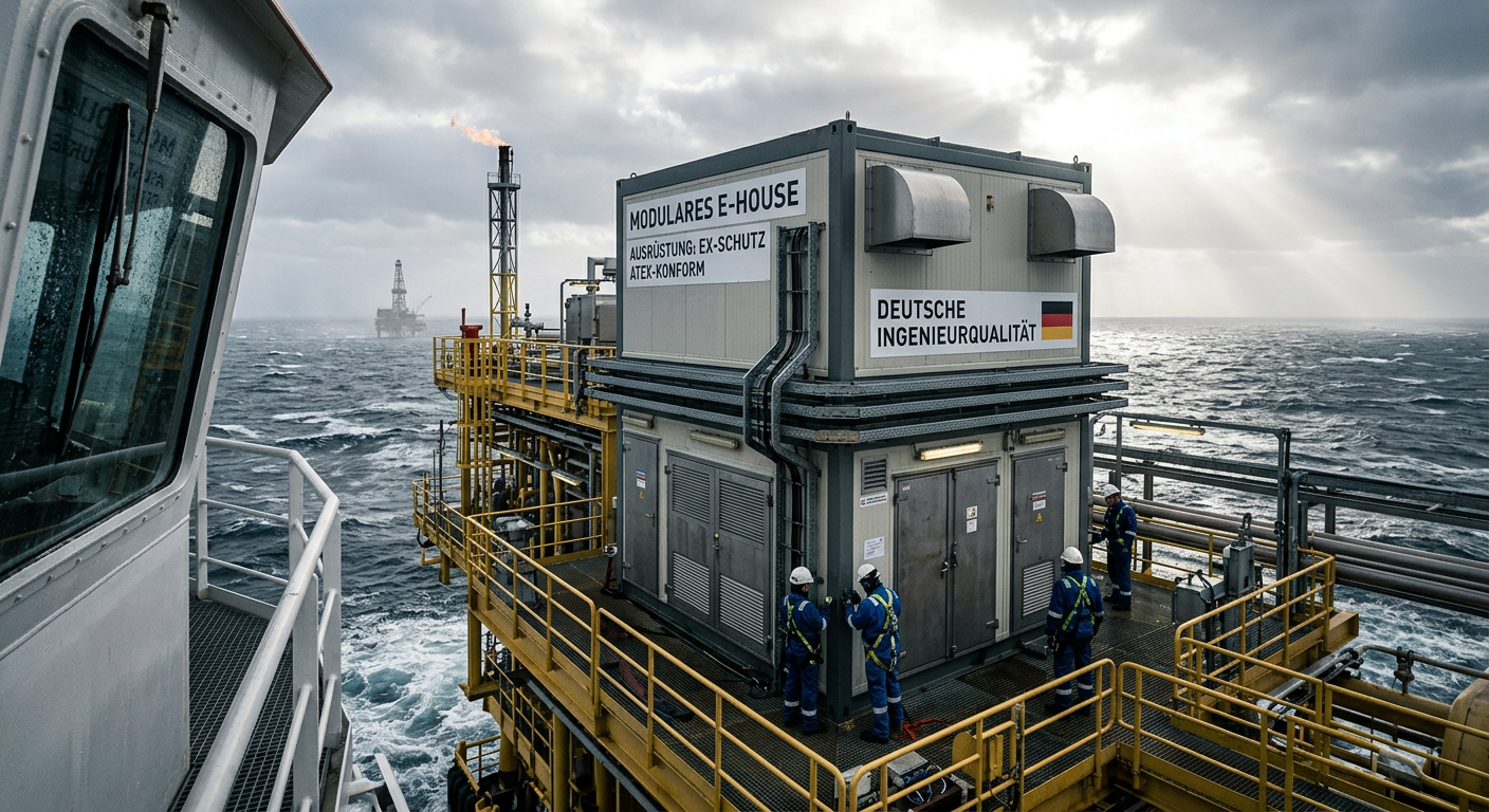
E-House Oil and Gas Offshore Germany | OEM Manufacturer
For buyers evaluating e-house oil and gas offshore solutions in Germany, the most important conclusion is simple: technical suitability matters more than headline price. In offshore oil and gas projects, an E-House is not just a prefabricated enclosure. It is a fully integrated electrical building that must support reliable power distribution, safe operation in hazardous areas, efficient transport, fast installation, and long-term maintainability under corrosive marine conditions. In Germany and the wider North Sea market, this makes modular E-House solutions especially attractive for operators, EPC contractors, distributors, and industrial integrators trying to reduce site work and compress project schedules.
-
![]()
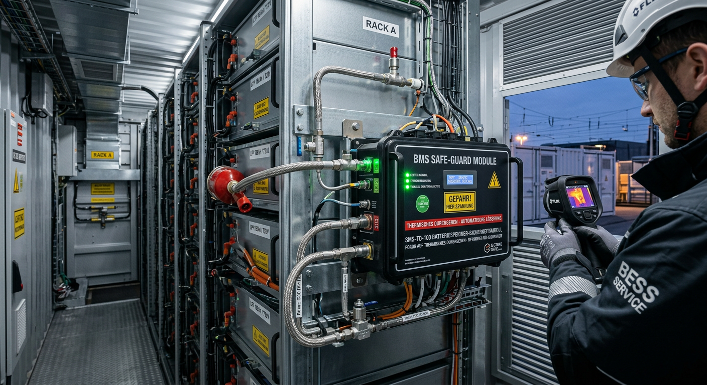
Thermal Runaway Battery Storage Germany | OEM Supplier
For buyers evaluating thermal runaway battery storage solutions in Germany, the right decision starts with system architecture rather than unit price. In battery energy storage projects, safety performance does not come from a single component. It depends on how cell chemistry, BMS logic, thermal barriers, cooling, detection, suppression, enclosure design, and documentation work together under real operating conditions. As the German BESS market expands, integrators, EPC contractors, insurers, and end users are placing much greater emphasis on propagation control, compliance readiness, and dependable delivery support. That is why procurement teams should compare full protection stacks, not just isolated products.
-
![]()
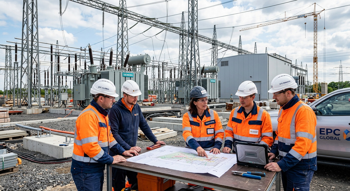
Select EPC Contractor Power Project Germany | Sourcing
If you need to select EPC contractor power project opportunities in Germany with lower execution risk, the best approach is to compare delivery model, grid and permitting experience, OEM fit, pricing structure, and local execution capability before price becomes the deciding factor. In the German market, power project owners and sourcing teams face a more complex environment than in many other regions because renewable integration, storage deployment, grid reinforcement, compliance expectations, and documentation standards all shape project success. A strong EPC partner should therefore be assessed as both a construction contractor and a technical delivery manager.
-
![]()
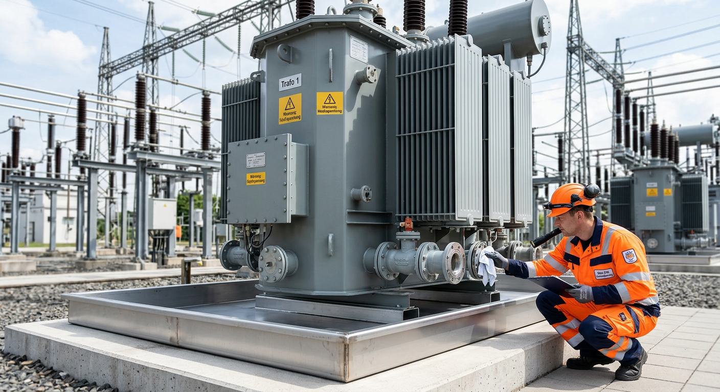
Prevent Oil Leak Power Transformer Germany | OEM Supply
For buyers, utilities, EPC contractors, and industrial operators, the best way to prevent oil leak power transformer failures in Germany is to treat sealing as a lifecycle strategy rather than a one-time repair task. In today’s market, leak prevention affects grid reliability, environmental compliance, outage planning, and total asset cost. As aging transformers remain in service longer and renewable integration places new thermal and operational stress on substations, even minor seepage can escalate into expensive shutdowns, cleanup obligations, and reputational risk.