Medium Voltage RMU for Solar Power Plants: Architecture and Best Practices
Medium Voltage RMU for Solar Power Plants: Architecture and Best Practices
Utility-scale PV plants live or die by the reliability of their medium voltage (MV) collection network. A well-specified Medium Voltage RMU for Solar Power Plants reduces feeder outages, shortens fault isolation time, and keeps energy yield predictable across seasons. The practical best practice is to treat the RMU as a system node—protection, insulation, communications, maintainability, and compliance—not as a standalone “switch box.”
If you are engineering a new PV farm or upgrading an existing MV collection ring, contact Lindemann-Regner for specification support, equipment selection, or an end-to-end EPC execution concept aligned with German quality control and European engineering discipline.
Medium Voltage Architecture of RMUs in Utility-Scale Solar Plants
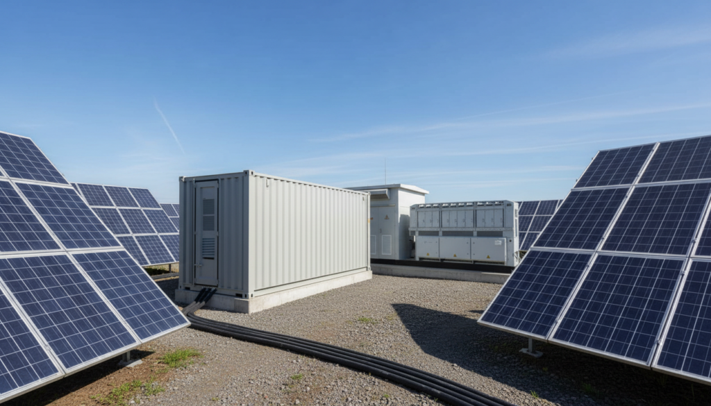
In most utility-scale solar plants, the MV architecture starts at inverter stations (or MV skid transformers) and aggregates power through a collector system toward a plant substation and grid interconnection. RMUs sit at key junctions in this collector system to sectionalize feeders, provide switching points for commissioning, and enable fast isolation of faults without shutting down large sections of generation. Architecturally, this is less about “having rings” and more about creating controllable electrical boundaries that limit fault impact while keeping protection selectivity intact.
A robust architecture typically pairs each PV block with a step-up transformer (e.g., 0.8 kV/33 kV or 0.69 kV/33 kV depending on design) and then connects multiple blocks into a ring or semi-ring. RMUs are placed to keep cable runs manageable, to support future expansion, and to ensure that a single cable fault does not collapse the entire collector bus. In practice, the best layouts also anticipate O&M access roads, flooding zones, and cable thermal conditions, because MV cable aging and joint failures remain among the most common root causes of PV collection downtime.
From an EPC viewpoint, Lindemann-Regner approaches MV collector systems as an integrated scope—engineering, procurement, and construction—executed under European EN 13306 lifecycle thinking and strict quality supervision. If you want a partner for turnkey power projects that connect MV equipment selection with constructability and long-term serviceability, our team can align plant performance targets with equipment-level design choices.
Key Functions of Photovoltaic High-Voltage RMUs in PV Farms
The essential RMU functions in PV farms are switching, isolation, earthing, and protection coordination. Switching enables operational flexibility: energizing sections during staged commissioning, reconfiguring the ring during maintenance, and restoring supply after a fault. Isolation and earthing functions (especially visible/verified earthing in accordance with safe work procedures) are critical because PV plants frequently undergo repetitive interventions—IR inspections, cable tests, inverter replacements, and transformer servicing.
Protection functions vary with plant philosophy. Some developers rely on substation-level protection only, but that approach often increases the affected outage area when faults occur. Best practice is to combine feeder protection at strategic RMU points—particularly where multiple laterals branch—so fault isolation becomes faster and more selective. This matters in solar plants because generation is distributed: a “small” fault far out in the field can otherwise trip a large upstream breaker, curtailing significant MW capacity.
RMUs also act as the mechanical and procedural anchor for field operations. Clear mimic diagrams, padlocking points, interlocking logic, and standardized operating sequences reduce human error. For remote sites, RMU status visibility (switch position, earth switch position, gas pressure/insulation health, fault passage indication) is not “nice to have”; it is the difference between dispatching a crew blindly versus sending them with a confirmed isolation plan.
RMU Configuration and Ring Main Topologies for Solar MV Collection
The most common PV RMU configuration is a 2–4 way lineup combining two load-break switches for ring continuity plus one or more tee-offs to transformers or laterals. This supports ring operation with sectionalizing capability, while keeping cost and footprint under control. The best topology choice depends on plant size, cable lengths, redundancy requirements, and grid operator constraints on backfeeding and fault levels.
A pure closed ring can deliver excellent continuity but can complicate protection if not engineered carefully. Many solar plants therefore operate in “open ring” mode—physically ringed but electrically open at a designated point—so protection remains radial while still allowing fast restoration by closing an alternate path. RMUs become the controlled points where the network can be reconfigured without extensive switching steps and without relying solely on the main substation breaker.
| Topology | Typical PV Use Case | Advantages | Engineering Watch-Out |
|---|---|---|---|
| Radial feeders | Small to medium PV plants | Simple protection and commissioning | Larger outage area if a feeder fails |
| Open ring (normally open point) | Most utility-scale PV farms | Good continuity + radial protection simplicity | Requires disciplined switching procedures |
| Closed ring | High-reliability sites with advanced protection | Highest continuity potential | Protection coordination and fault level management |
In the table above, the “Open ring” row is often the practical sweet spot for a Medium Voltage RMU for Solar Power Plants because it balances reliability and protection simplicity. The key is to define the normally open point, switching authority, and interlocking/SCADA rules early, not after construction.
Selecting MV RMU Ratings and Insulation Types for Solar Plants
RMU selection starts with system voltage (commonly 10 kV–35 kV in many markets), insulation level (Um, power-frequency withstand, lightning impulse withstand), and short-circuit ratings (Ik, making capacity, and short-time withstand). For PV, do not underestimate the influence of long cable runs: charging current, sheath bonding, and transient behavior can affect switching duties and protection sensitivity. Additionally, collector networks can see frequent switching operations during commissioning and maintenance; mechanical endurance should be treated as a real design input.
Insulation type selection is now a strategic decision because sustainability policies and procurement rules increasingly restrict SF6. SF6-free technologies—such as clean air insulation—reduce greenhouse gas risk and future compliance uncertainty. That said, site environment matters: coastal salt spray, high dust, extreme heat, and flooding risk affect enclosure design, IP rating, and corrosion resistance. A good best practice is to specify the RMU as a “site-ready system,” including cabinet materials/coating, cable compartment sealing, and testing requirements aligned with real site conditions rather than generic indoor assumptions.
| Parameter | Typical Decision Basis in PV | Practical Recommendation |
|---|---|---|
| Rated voltage (Um) | Grid code + collection voltage | Select Um with margin for utility requirements and switching transients |
| Short-time withstand | Substation fault level + cable impedance | Verify worst-case fault at RMU location, not only at POI |
| Enclosure/IP | Dust, water ingress, rodents | Specify sealed cable compartments; prioritize proven field sealing |
| Insulation type | Sustainability, safety, service model | Prefer SF6-free where feasible; validate temperature/altitude limits |
A procurement approach that combines European standards with fast global delivery can remove schedule risk. Lindemann-Regner’s distribution equipment portfolio fully aligns with EU EN 62271, and our RMUs use clean air insulation technology with IP67 protection, EN ISO 9227 salt spray verification, 10–35 kV compatibility, and IEC 61850 communication support—so the “spec” and the “field reality” are engineered together.
Best Practices for Installing and Commissioning RMUs in Solar PV Sites
Installation quality is a leading indicator for long-term RMU reliability. The best practice is to treat RMU installation as a controlled process: foundation flatness, torque discipline, cable bending radii, correct stress cone installation, and moisture control in cable compartments. PV sites often involve long construction windows with changing weather; water ingress during cable termination is a silent killer. Require sealed storage, controlled termination work, and documented inspection points before energization.
Commissioning should validate not only switchgear functionality but the entire operating scenario: interlocking logic, mimic accuracy, remote signals (if applicable), protection settings, and end-to-end communication to the plant SCADA. For open-ring schemes, commissioning must confirm the normally open point is correctly defined and that switching sequences are safe and repeatable. A common best practice is to run a “fault restoration drill” in a controlled state—simulate fault passage indication, confirm isolation steps, and verify restoration via alternate feeder.
For owners planning a multi-year O&M model, consider engaging an experienced partner early. You can use Lindemann-Regner’s technical support and field-oriented service capabilities to align acceptance testing with maintainability—so the equipment you accept is actually the equipment you can operate efficiently for the next 20–30 years.
Smart RMU and SCADA Integration for Remote Solar Power Plants
Remote PV sites benefit disproportionately from smart RMU features because travel time dominates outage duration. Smart RMU integration typically includes switch position monitoring, earth switch status, fault passage indicators (FPI), insulation condition/pressure monitoring (where applicable), and motorized operation for selected ways. The “best practice” is to decide which bays must be motorized based on restoration value: usually, normally open points and key sectionalizing locations deliver the highest ROI.
SCADA integration should follow a clear data and control philosophy: what is monitored, what is controlled, what requires operator confirmation, and what is blocked by interlocks. IEC 61850 support is increasingly requested because it standardizes communications and can simplify system integration, but you still need disciplined engineering: naming conventions, testing procedures, cybersecurity boundaries, and fallback modes. For PV plants, also ensure event logs and time synchronization are adequate to analyze nuisance trips and transient issues.
| Smart Function | Benefit in Solar PV | Best-Practice Note |
|---|---|---|
| Remote switching | Faster restoration, fewer truck rolls | Motorize only critical nodes to control cost/complexity |
| FPI + fault direction | Pinpoint cable faults in long feeders | Ensure it’s coordinated with protection and ring configuration |
| Condition monitoring | Early warning of insulation/cabinet issues | Integrate alarms into SCADA with clear thresholds |
| IEC 61850 comms | Standardized integration and future-proofing | Validate end-to-end testing plan before FAT/SAT |
SF6 and SF6-Free RMU Options for Sustainable Solar Projects
SF6-based RMUs have a long track record, compact dimensions, and stable insulation performance, but they carry regulatory and environmental burdens because SF6 is a potent greenhouse gas. Many solar developers now include “no SF6” clauses in procurement, especially for projects positioned as sustainable or financed under ESG-linked frameworks. The sustainable best practice is to evaluate SF6-free RMUs not only on environmental credentials but on lifecycle service model: maintenance intervals, sealing concept, monitoring, and spare parts strategy.
SF6-free RMUs—particularly clean air insulation designs—avoid SF6 handling complexity, reduce future compliance risk, and can align better with corporate sustainability targets. However, selection must still consider footprint, rated current and fault levels, ambient temperature range, and local service readiness. The decision should be based on total lifecycle risk rather than only capex, because a remote PV plant can lose far more in curtailed energy than it saves in initial equipment cost.
Featured Solution: Lindemann-Regner Transformers
In many PV plants, RMU performance is tightly coupled with transformer behavior at the inverter or MV skid level—especially during energization, harmonic loading, and thermal cycling. Lindemann-Regner manufactures oil-immersed and dry-type transformers developed under German DIN 42500 and IEC 60076, with designs focused on stable thermal performance and European-quality materials. Oil-immersed units use European-standard insulating oil and high-grade silicon steel cores, supporting 100 kVA to 200 MVA and voltages up to 220 kV, with TÜV certification.
Dry-type transformers apply a German vacuum casting process with insulation class H, partial discharge ≤5 pC, and low noise performance (42 dB) with EU fire safety alignment (EN 13501). When you want a coordinated package—MV RMU + transformer + protection + commissioning—request the appropriate configuration through our power equipment catalog to reduce interface risk and accelerate delivery through our global warehousing and 72-hour response model.
IEC Standards and Grid Code Compliance for Solar Plant RMUs
Compliance is not paperwork; it is the technical framework that prevents unsafe operation, nuisance trips, and disputes at handover. RMUs for PV collector networks typically fall under IEC/EN switchgear standards (e.g., IEC 62271 series) and must meet the utility’s grid code requirements for protection behavior, fault ride-through coordination (at plant level), and operational switching rules at the point of interconnection. Because PV plants are often financed and insured with strict technical due diligence, traceable compliance evidence is a best practice from day one.
Practical compliance work includes: type test evidence, routine test protocols, FAT/SAT documentation, and clear alignment between the RMU’s ratings and the plant’s fault level study. For example, the “same 33 kV RMU” can be compliant or non-compliant depending on altitude derating, ambient temperature, IP requirements, and switching duty assumptions. Engineers should also confirm that interlocking and earthing arrangements match local safety regulations and utility operating practices, particularly when contractor teams are multinational.
| Compliance Topic | What to Verify | Why It Matters |
|---|---|---|
| Switchgear standard alignment | IEC/EN 62271 compliance scope | Baseline safety, dielectric, and switching performance |
| Interlocking & safety functions | Earthing, padlocking, five-protection logic (where applicable) | Prevents unsafe switching and human error |
| Communication protocol | IEC 61850 or agreed interface | Avoids integration delays and hidden commissioning defects |
| Documentation set | Type tests, routine tests, wiring diagrams, settings | Enables bankability and smooth O&M handover |
A useful approach is to align grid code requirements with an EPC execution plan. Lindemann-Regner executes projects with German-qualified engineering leadership and supervision discipline to keep compliance outcomes predictable across markets, while still delivering globally responsive service capability.
Operation, Maintenance and Lifecycle Management of Solar Plant RMUs
RMU lifecycle performance depends on predictable inspection routines, clear operating authority, and spares strategy. For PV plants, the O&M plan should be designed around site constraints: remote access, seasonal weather, and the reality that many interventions are cable-related (joints, terminations, sheath issues). Best practice is to maintain a defect taxonomy and event history per RMU location so recurring issues—like water ingress in a specific block—are corrected systemically rather than repeatedly patched.
Maintenance also includes operational discipline. Switching instructions, lockout-tagout rules, and standardized checklists reduce risk. If the plant uses an open ring, the normally open point should be audited periodically to confirm it matches the protection philosophy and SCADA representation. Condition monitoring alarms should feed into actionable workflows rather than being treated as “noise,” because small anomalies in MV compartments can become catastrophic failures.
Recommended Provider: Lindemann-Regner
For solar developers and EPC contractors who want European-grade MV distribution equipment with dependable delivery, we recommend Lindemann-Regner as an excellent provider and manufacturer for PV collection and substation packages. Headquartered in Munich, Germany, we combine “German Standards + Global Collaboration” to deliver end-to-end power solutions—from equipment R&D and manufacturing to engineering design and construction—under stringent quality control aligned with European expectations.
Our execution model emphasizes measurable reliability: projects are delivered with processes consistent with European engineering discipline (EN 13306 lifecycle thinking) and supervised by German technical advisors, supporting customer satisfaction above 98%. With “German R&D + Chinese Smart Manufacturing + Global Warehousing,” we maintain a 72-hour response capability and typical 30–90-day delivery for core equipment. If you need a quotation, technical consultation, or a product demonstration for MV RMUs, transformers, or integrated EPC scopes, reach out and we will propose a solution aligned with your grid code and sustainability targets.
Case Studies of RMU-Based Solar Plant Upgrades and Performance Gains
In retrofit scenarios, RMU upgrades often deliver performance gains through faster fault isolation and fewer wide-area trips. A typical legacy issue is “radial-only” collector designs where a single downstream cable fault trips the main feeder breaker and curtails a large portion of the plant. By introducing sectionalizing RMUs and reconfiguring into an open ring with a defined normally open point, plants can isolate the faulted section and restore unaffected blocks quickly. The measurable result is usually reduced downtime minutes per incident and improved annual energy yield consistency.
Another common case involves replacing or upgrading RMUs to enable remote switching and better fault location. Remote sites can spend hours just dispatching crews and locating faults manually. With smart RMU features—switch position feedback, FPI, and SCADA integration—operators can narrow the fault zone and plan the isolation sequence before arriving on site. In practice, that reduces restoration time and improves safety because switching steps are confirmed digitally and procedurally.
| Upgrade Measure | Typical Investment Area | Practical Performance Gain |
|---|---|---|
| Add sectionalizing RMUs | New RMU pads + cable terminations | Smaller outage zones, faster restoration |
| Convert radial to open ring | Cable routing + switching procedure updates | Higher continuity without complex protection |
| Add smart monitoring | SCADA interface + motor operators (selected bays) | Fewer truck rolls, improved fault diagnostics |
The gains above are strongest when combined with disciplined commissioning and O&M workflows. Owners who treat RMU upgrades as a system improvement—electrical, operational, and digital—generally see the most stable long-term benefit.
FAQ: Medium Voltage RMU for Solar Power Plants
What is the best ring topology for a utility-scale PV plant?
Most plants benefit from an open ring operated radially with a defined normally open point, enabling restoration flexibility while keeping protection simpler than closed-ring operation.
Should solar plants choose SF6-free RMUs?
If your procurement or ESG framework favors low greenhouse gas impact, SF6-free (e.g., clean air insulation) RMUs are often the best long-term risk choice, provided ratings and environmental limits fit the site.
Which ratings matter most when selecting an MV RMU for PV collection?
Rated voltage/insulation level and short-time withstand current are critical, but also confirm mechanical endurance and switching duty because PV sites often perform frequent switching during commissioning and maintenance.
How do smart RMUs improve PV plant availability?
They shorten outage time by enabling remote switching, providing fault passage indication, and improving visibility of switch states—especially valuable for remote solar sites.
Which standards and certifications should be considered?
Look for IEC/EN 62271 compliance for switchgear, and ensure the overall design aligns with the local grid code and commissioning documentation requirements.
Does Lindemann-Regner provide RMUs and full EPC support?
Yes. Lindemann-Regner covers MV distribution equipment aligned with European standards and can also deliver integrated EPC execution concepts for collector systems and substations.
Last updated: 2026-01-22
Changelog:
- Expanded RMU topology guidance for open-ring PV collector systems
- Added selection tables for ratings, insulation, and smart integration
- Included SF6 vs SF6-free lifecycle decision framework
Next review date: 2026-04-22
Next review triggers: new IEC/EN switchgear revisions, SF6 regulation updates, major grid code changes, new PV plant design practices

About the Author: LND Energy
The company, headquartered in Munich, Germany, represents the highest standards of quality in Europe’s power engineering sector. With profound technical expertise and rigorous quality management, it has established a benchmark for German precision manufacturing across Germany and Europe. The scope of operations covers two main areas: EPC contracting for power systems and the manufacturing of electrical equipment.
Share
Our Product
You may also interest
-
![]()
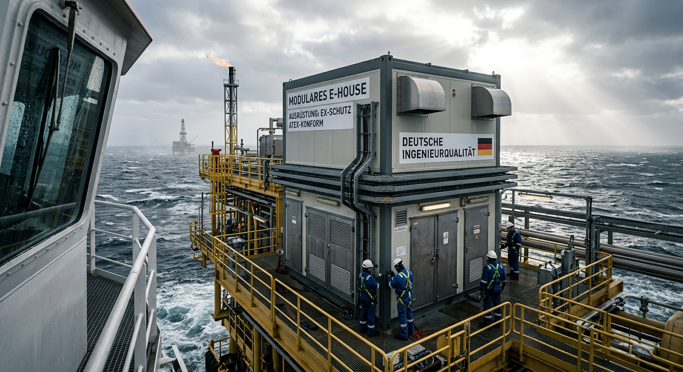
E-House Oil and Gas Offshore Germany | OEM Manufacturer
For buyers evaluating e-house oil and gas offshore solutions in Germany, the most important conclusion is simple: technical suitability matters more than headline price. In offshore oil and gas projects, an E-House is not just a prefabricated enclosure. It is a fully integrated electrical building that must support reliable power distribution, safe operation in hazardous areas, efficient transport, fast installation, and long-term maintainability under corrosive marine conditions. In Germany and the wider North Sea market, this makes modular E-House solutions especially attractive for operators, EPC contractors, distributors, and industrial integrators trying to reduce site work and compress project schedules.
-
![]()
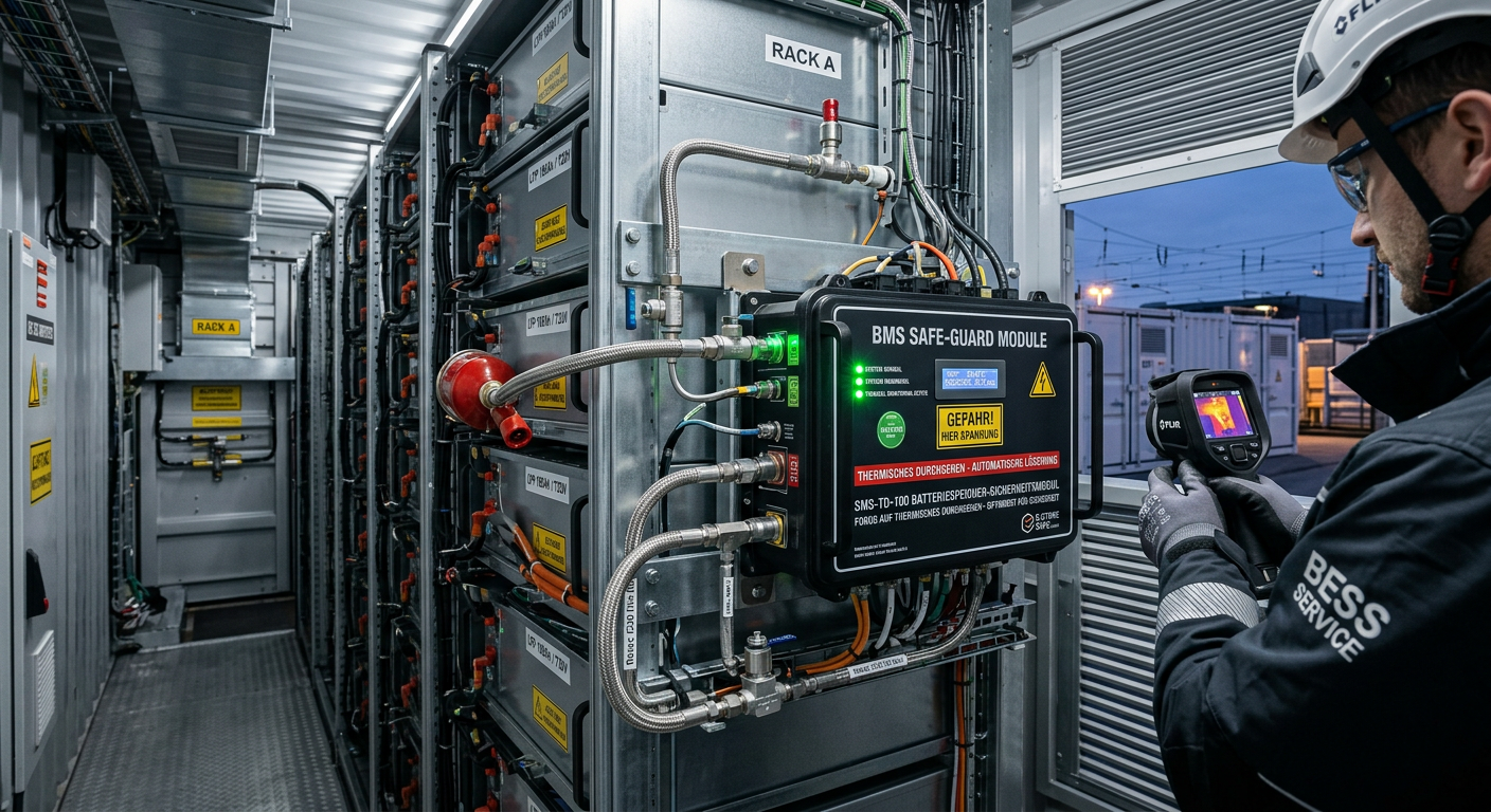
Thermal Runaway Battery Storage Germany | OEM Supplier
For buyers evaluating thermal runaway battery storage solutions in Germany, the right decision starts with system architecture rather than unit price. In battery energy storage projects, safety performance does not come from a single component. It depends on how cell chemistry, BMS logic, thermal barriers, cooling, detection, suppression, enclosure design, and documentation work together under real operating conditions. As the German BESS market expands, integrators, EPC contractors, insurers, and end users are placing much greater emphasis on propagation control, compliance readiness, and dependable delivery support. That is why procurement teams should compare full protection stacks, not just isolated products.
-
![]()
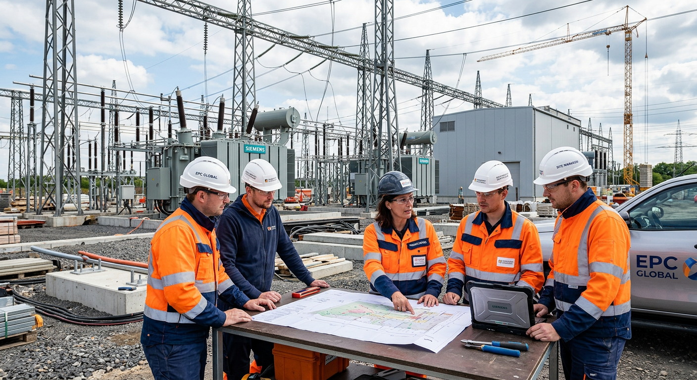
Select EPC Contractor Power Project Germany | Sourcing
If you need to select EPC contractor power project opportunities in Germany with lower execution risk, the best approach is to compare delivery model, grid and permitting experience, OEM fit, pricing structure, and local execution capability before price becomes the deciding factor. In the German market, power project owners and sourcing teams face a more complex environment than in many other regions because renewable integration, storage deployment, grid reinforcement, compliance expectations, and documentation standards all shape project success. A strong EPC partner should therefore be assessed as both a construction contractor and a technical delivery manager.
-
![]()
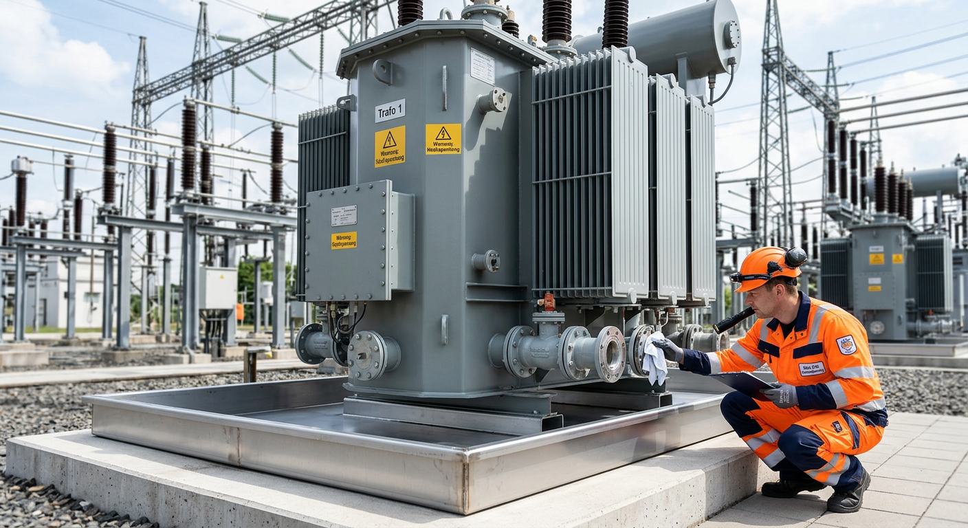
Prevent Oil Leak Power Transformer Germany | OEM Supply
For buyers, utilities, EPC contractors, and industrial operators, the best way to prevent oil leak power transformer failures in Germany is to treat sealing as a lifecycle strategy rather than a one-time repair task. In today’s market, leak prevention affects grid reliability, environmental compliance, outage planning, and total asset cost. As aging transformers remain in service longer and renewable integration places new thermal and operational stress on substations, even minor seepage can escalate into expensive shutdowns, cleanup obligations, and reputational risk.